Network Video Recorder Quick Start Guide
17
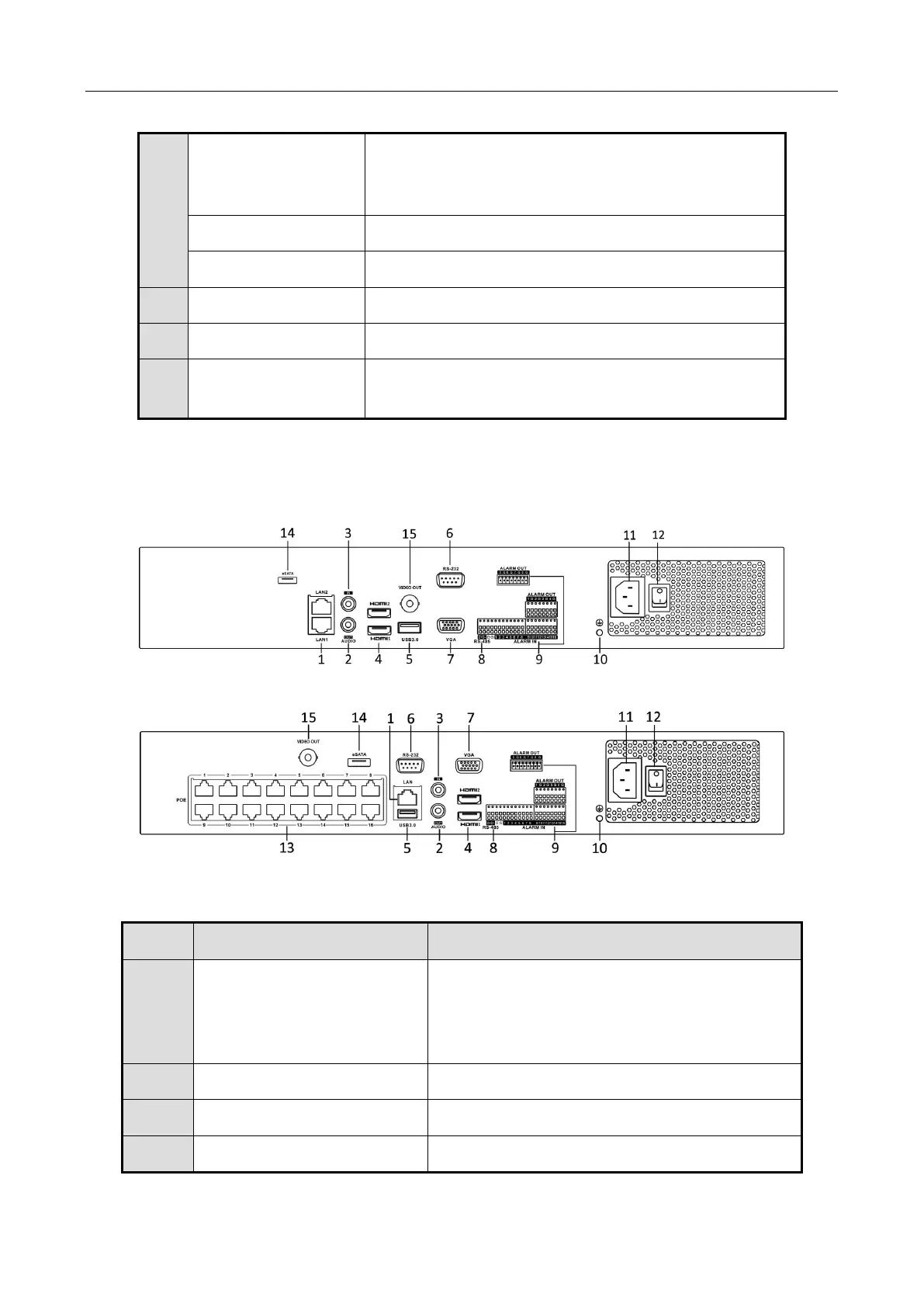
1.2.4 iDS-7700NXI-I4/(16P)/16S(B) Series
Figure 1-11 iDS-7700NXI-I4/16S(B) Series Rear Panel
Figure 1-12 iDS-7700NXI-I4/16P/16S(B) Series Rear Panel
Table 1-9 Panel Description
D+, D- pin connects to Ta, Tb pin of controller. For
cascading devices, the first NVR’s D+, D- pin should
be connected with the D+, D- pin of the next NVR.
Connector for alarm input.
Connector for alarm output.
100 to 240 VAC power supply.
Switch for turning on/off the device.
Ground (needs to be connected when NVR starts
up).
1 network interface provided by
iDS-7700NXI-I4/16P/16S(B) series, and 2
network interfaces by iDS-7700NXI-I4/16S(B)
series.
RCA connector for audio output.
RCA connector for audio input.
HDMI video output connector.
 Loading...