EasyManuals Logo

HIKVISION iDS-96128NXI-I24 User Manual

HIKVISION iDS-96128NXI-I24
44 pages
To Next Page IconTo Next Page
To Previous Page IconTo Previous Page
Page #17 background imageLoading...
Page #17 background image
Network Video Recorder Quick Start Guide
16
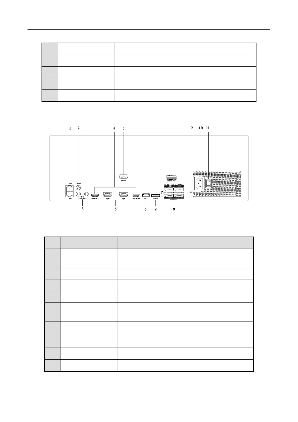
1.2.3 iDS-9600NXI-I16/8F(B) and iDS-9600NXI-I16/16S(B) Series
Figure 1-10 Rear Panel
Table 1-8 Panel Description
ALARM IN
Connector for alarm input.
ALARM OUT
Connector for alarm output.
10
100 to 240 VAC
100 to 240 VAC power supply.
11
Power Switch
Switch for turning on/off the device.
12
GROUND
Ground (needs to be connected when NVR starts up).
No.
Name
Description
1
LAN1/LAN2
Interface
2 RJ-45 10/100/1000 Mbps self-adaptive Ethernet
interfaces provided.
2
LINE IN
RCA connector for audio input.
3
AUDIO OUT
2 RCA connectors for audio output.
4
HDMI1/HDMI2
HDMI video output connector.
5
VGA1/VGA2
DB9 connector for VGA output. Display local video
output and menu.
6
USB 3.0 interface
Universal Serial Bus (USB) ports for additional
devices such as USB mouse and USB Hard Disk Drive
(HDD).
7
RS-232 Interface
Connector for RS-232 devices.
8
eSATA
Connects external SATA HDD, CD/DVD-RM.

Questions and Answers:

Question and Answer IconNeed help?

Do you have a question about the HIKVISION iDS-96128NXI-I24 and is the answer not in the manual?

HIKVISION iDS-96128NXI-I24 Specifications

General IconGeneral
BrandHIKVISION
ModeliDS-96128NXI-I24
CategoryNetwork Hardware
LanguageEnglish

Related product manuals