EasyManuals Logo

HIKVISION iDS-96128NXI-I24 User Manual

HIKVISION iDS-96128NXI-I24
44 pages
To Next Page IconTo Next Page
To Previous Page IconTo Previous Page
Page #21 background imageLoading...
Page #21 background image
Network Video Recorder Quick Start Guide
20
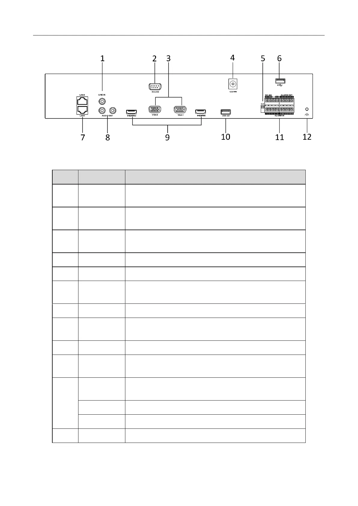
Figure 1-14 iDS-6700NXI-I/8F(B) Series Rear Panel
Table 1-11 Interface Description
Index
Item
Description
1
LINE IN
3.5mm interface for line in; connect to audio input device
or active pick-up, microphone, etc.
2
RS-232
Serial interface for configuration of device’s parameters or
used as transparent channel.
3
VGA
DB9 connector for VGA output. Display local video output
and menu.
4
DC12V
12 VDC power supply
5
SW
SW dial switch
6
USB 2.0
Interface
Universal Serial Bus (USB) ports for additional devices such
as USB mouse and USB Hard Disk Drive (HDD).
7
LAN1/LAN2
10/100/1000 Mbps self-adaptive Ethernet interface
8
AUDIO OUT
3.5mm interface; connect to audio output device, e.g.,
loudspeaker, etc.
9
HDMI
HDMI video output connector.
10
USB 2.0
Interface
Universal Serial Bus (USB) ports for additional devices such
as USB mouse and USB Hard Disk Drive (HDD).
11
RS-485
RS-485 serial interface; connect to pan/tilt unit, speed
dome, etc.
ALARM IN
Relay alarm input.
ALARM OUT
Relay alarm output.
12
GND
Grounding

Questions and Answers:

Question and Answer IconNeed help?

Do you have a question about the HIKVISION iDS-96128NXI-I24 and is the answer not in the manual?

HIKVISION iDS-96128NXI-I24 Specifications

General IconGeneral
BrandHIKVISION
ModeliDS-96128NXI-I24
CategoryNetwork Hardware
LanguageEnglish

Related product manuals