EasyManuals Logo

Hill-Rom VersaCare P3200 Service Manual

Hill-Rom VersaCare P3200
379 pages
To Next Page IconTo Next Page
To Previous Page IconTo Previous Page
Page #231 background imageLoading...
Page #231 background image
4.32 IntelliDrive® Transport System Interface P.C. Board
Chapter 4: Removal, Replacement, and Adjustment Procedures
4.32 IntelliDrive® Transport System Interface P.C. Board
Tools required: T25 Torx®
1
screwdriver
Removal
1. Set the brakes.
SHOCK HAZARD:
Unplug the bed from its power source. Failure to do so could result in
personal injury or equipment damage.
2. Unplug the bed from its power source.
3. Remove the six screws (A) securing the power supply cover (B) to the bed
(C)
(see figure 4-51 on page 4-99).
Figure 4-51. Interface P.C. Board
4. Remove the power supply cover (B).
1. Torx® is a registered trademark of Textron, Inc.
4
VersaCare™ Bed Service Manual (MAN333 REV 2) Page 4 - 99

Table of Contents

Questions and Answers:

Question and Answer IconNeed help?

Do you have a question about the Hill-Rom VersaCare P3200 and is the answer not in the manual?
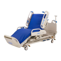
Hill-Rom VersaCare P3200 Specifications

General IconGeneral
TypeHospital Bed
Trendelenburg PositionYes
Reverse Trendelenburg PositionYes
Side RailsYes, integrated
Power SourceElectric
Wheel TypeLocking casters
Height Adjustment15" - 30"
Maximum Head Elevation70 degrees
Maximum Knee Elevation40 degrees
Height Adjustability15" - 30"
Head and Foot AdjustmentYes
Weight Capacity500 lbs

Related product manuals