9 Configuring Communication HIMatrix
Page 62 of 72 HI 800 023 E Rev. 1.01
T
R
= t
1
+ t
2
+ t
3
T
R
Worst case reaction time
t
1
2 * watchdog time of the HIMatrix controller 1.
t
2
ReceiveTMO
t
3
2 * watchdog time of the HIMatrix controller 2.
The worst case reaction time depends on the process and must be agreed upon together
with the test authority responsible for the final inspection.
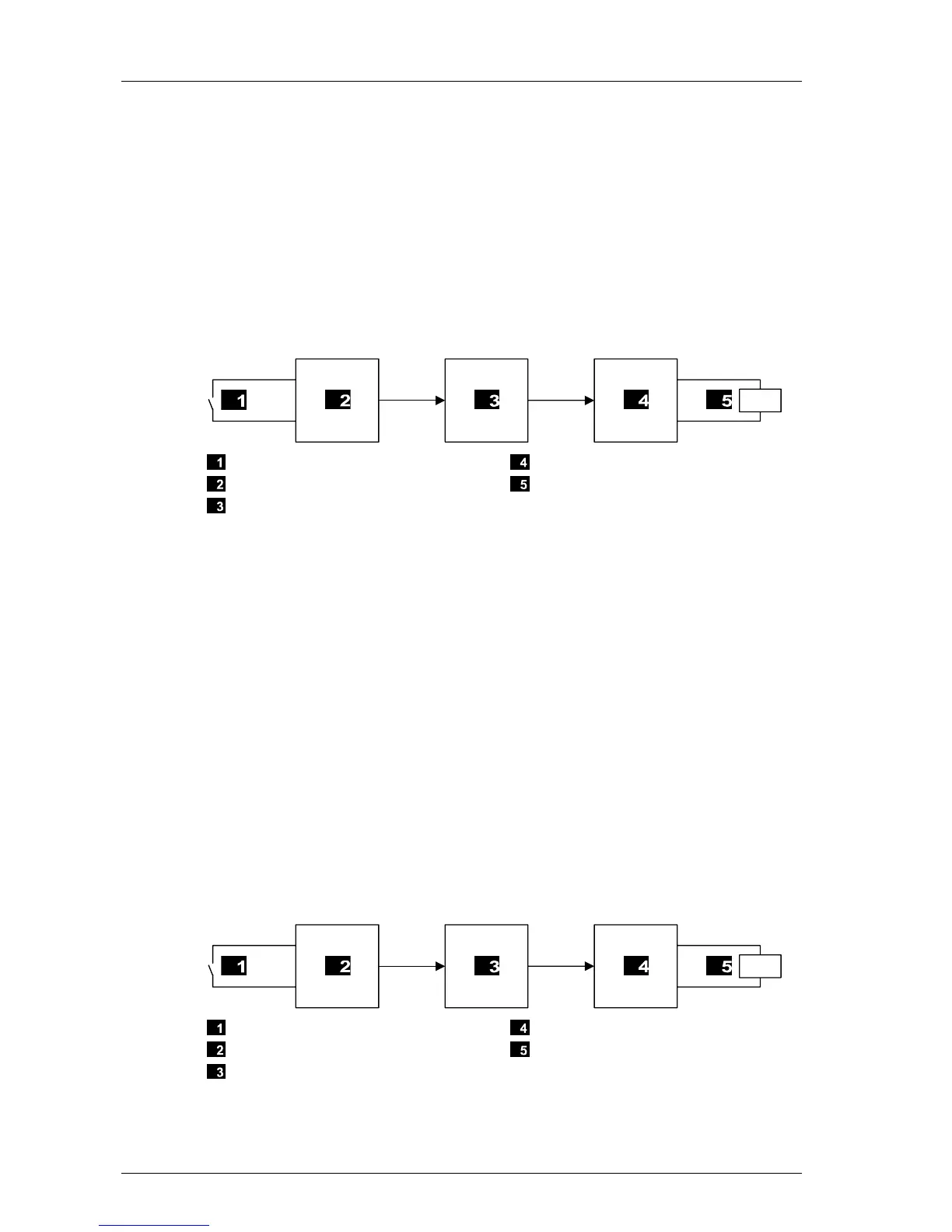
9.2.5 Calculating the Worst Case Reaction Time with two Remote I/Os
The worst case reaction time TR is the time between a change on the sensor input signal of
the first HIMatrix PES or Remote I/O (e.g., F3 DIO 20/8 01) and a reaction on the
corresponding output of the second HIMatrix PES or Remote I/O. It is calculated as follows:
Input
Remote I/O 1
HIMatrix Controller
Remote I/O 2
Output
Figure 5: Reaction Time with Remote I/Os
T
R
= t
1
+ t
2
+ t
3
+ t
4
+ t
5
T
R
Worst case reaction time
t
1
2 * watchdog time of remote I/O 1
t
2
ReceiveTMO
1
t
3
2 * watchdog time of the HIMatrix controller.
t
4
ReceiveTMO
2
t
5
2 * watchdog time of remote I/O 2
Note: Remote I/O 1 and remote I/O 2 can also be identical. The time values still apply if a
HIMatrix controller is used instead of a remote I/O.
9.2.6 Calculating the Worst Case Reaction Time with two HIMatrix and one
HIMax Controller
The worst case reaction time TR is the time between a change on the sensor input signal
(in) of the first HIMax PES and a reaction on the corresponding output (out) of the second
HIMax PES. It is calculated as follows
Input
HIMatrix Controller 1
HIMax Controller
HIMatrix Controller 2
Output
Figure 6: Reaction Time with Two HIMatrix Controllers and One HIMax Controller
 Loading...


