2. Pressing the RESET button eliminates the acoustic warning. The RESET LED
remains LIT and the type of warning is shown on the display (which stops
ashing). Warning “A”. (8)
3. This type of warning is auto reset automatically whenever normal operating
conditions are restored. It focuses on the alarms related to the fuel level as part
of the default programming and the alarm corresponding to the network
thresholds.
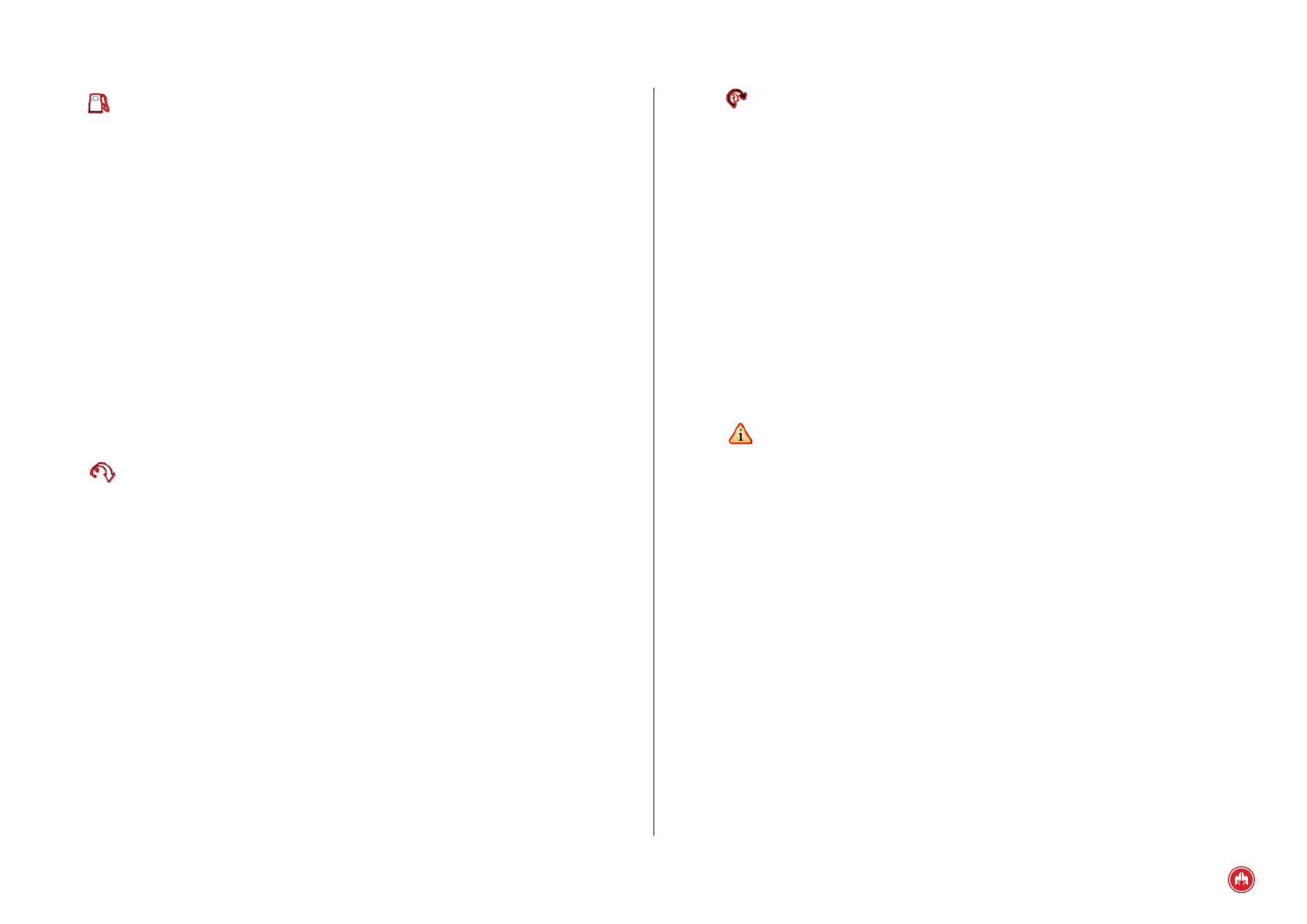
WARNING
FUEL RESERVE
Fig.8
3. We provide solutions for the warning. In this case, we stop the engine if we
believe this is necessary to detect the cause of the anomaly. Once the warning is
no longer active, "N" appears on the display and it can be reset by pressing the
RESET button. (6)
NOTICE
HIGH WATER
TEMPERATURE
Fig.6
“A” AUTO-RESETTABLE WARNING
1. Upon detection of an alarm or warning, the control unit produces an acoustic
signal, the LED of the RESET button and the display ashes and the alarm digital
output (AL) is activated. (7)
Fig.7
CEM7 CONTROL UNIT ALARMS | PAGE 36