Appendix 8 Zero Adjustment
A10
Zero adjustment is a function which adjusts the zero point by deducting the
residual value obtained during 0 measurement. For this reason, zero adjust-
ment must be performed when connection is made to 0 . However, connecting
a sample with no resistance is difficult and therefore is not practical.
In this respect, when performing the actual zero adjustment, create a pseudo
connection to 0 and then adjust the zero point.
To create 0 connection state
If an ideal 0 connection is made, the voltage between SENSE-H and SENSE-
L becomes 0 V according to the Ohm's Law of
E = I × R. In other words, if you
set the voltage between SENSE-H and SENSE-L to 0 V, this gives you the same
state of 0 connection.
To perform zero adjustment using the instrument
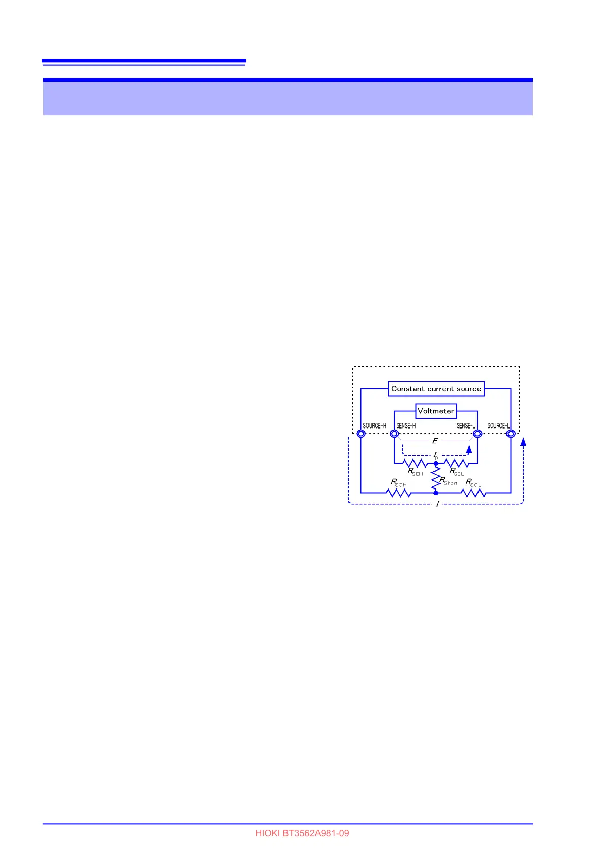
The instrument uses a measurement fault detection function to monitor the state
of connection between the four measurement terminals. For this reason, when
performing zero adjustment, you need to make connections between the termi-
nals appropriately in advance (Figure 1).
First, short between SENSE-H and
SENSE-L to set the voltage between
SENSE-H and SENSE-L to 0 V. If
lead resistances
R
SEH
and R
SEL
of
the cable are less than few , there
will be no problem. Because the
SENSE terminal is a voltage mea-
surement terminal, almost no cur-
rent
I
0
flows. Therefore, in the E = I
0
× (R
SEH
+ R
SEL
) formula, I
0
0 is
achieved; if lead resistances
R
SEH
and R
SEL
are less than few , volt-
age between SENSE-H and
SENSE-L will become almost zero.
Next, make connection between
SOURCE-H and SOURCE-L. This is
to avoid display of error when no
measurement current flows through.
Lead resistances
R
SOH
and R
SOL
of the cable must be less than the resistance
for flowing measurement current.
Furthermore, if you also monitor the connection between SENSE and SOURCE,
you need to make connection between SENSE and SOURCE. If lead resistance
R
Short
of the cable has only few , there will be no problem.
If you wire in the way described above, measurement current
I flowing out from
SOURCE-H will go to SOURCE-L but not to the lead of SENSE-H or SENSE-L.
This enables the voltage between SENSE-H and SENSE-L to be kept accurately
at 0 V, and appropriate zero adjustment becomes possible.
Appendix 8 Zero Adjustment
E
= (
I
0
×
R
SE L
) + (
I
0
×
R
SEH
)
= (0 ×
R
SE L
) + (0 ×
R
SEH
)
= 0 [V]
Figure 1 Pseudo connection to 0