Appx.3
Measurement Principle
Appx. 2 Measurement Principle
(1) 3-pole method (precise measurement)
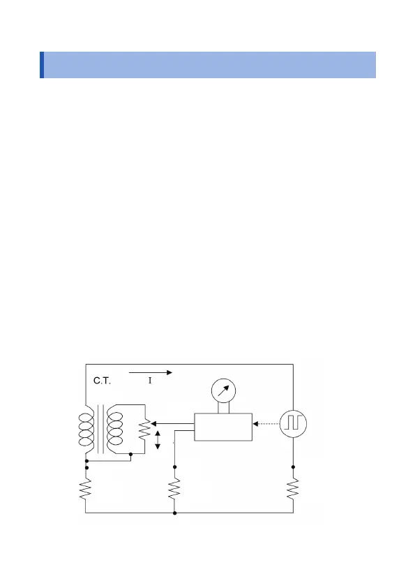
The gure below shows the basic circuit principle for earth
resistance measurement.
The measurement current I, driven by the oscillating voltage of the
oscillator, ows through the loop formed in the following order: the
oscillator, Rc, Rx, and C.T.
Where the voltage between the measurement terminals E and S(P)
is given by Ex; the resistance between the measurement terminal E
and the slider S of the variable resistor, by Rs; and the voltage drop
at the variable resistor, by Es, if the galvanometer is balanced, the
following equations then apply:
Ex = IRx
Es = IRs/n (n: C.T. winding ratio)
Ex = Es
Hence
Rx = Rs/n
Then, if the dial connected directly to the sliding resistor has a scale
of 1/n for Rs, the dial reading corresponds to the earth resistance
Rx.
Galvanometer
Synchronous
rectier
Oscillator
S(P)
1:n
H(C)
Rp
RcRx
E
S
Rs
Measurement principle diagram (3-pole measurement)
Ind.Appx.
7
6
5
4
3
2
1