2.2
RS-232C Connection and Settings
7
Chapter 2 Model IM3570/ IM3536 Connection and Setting
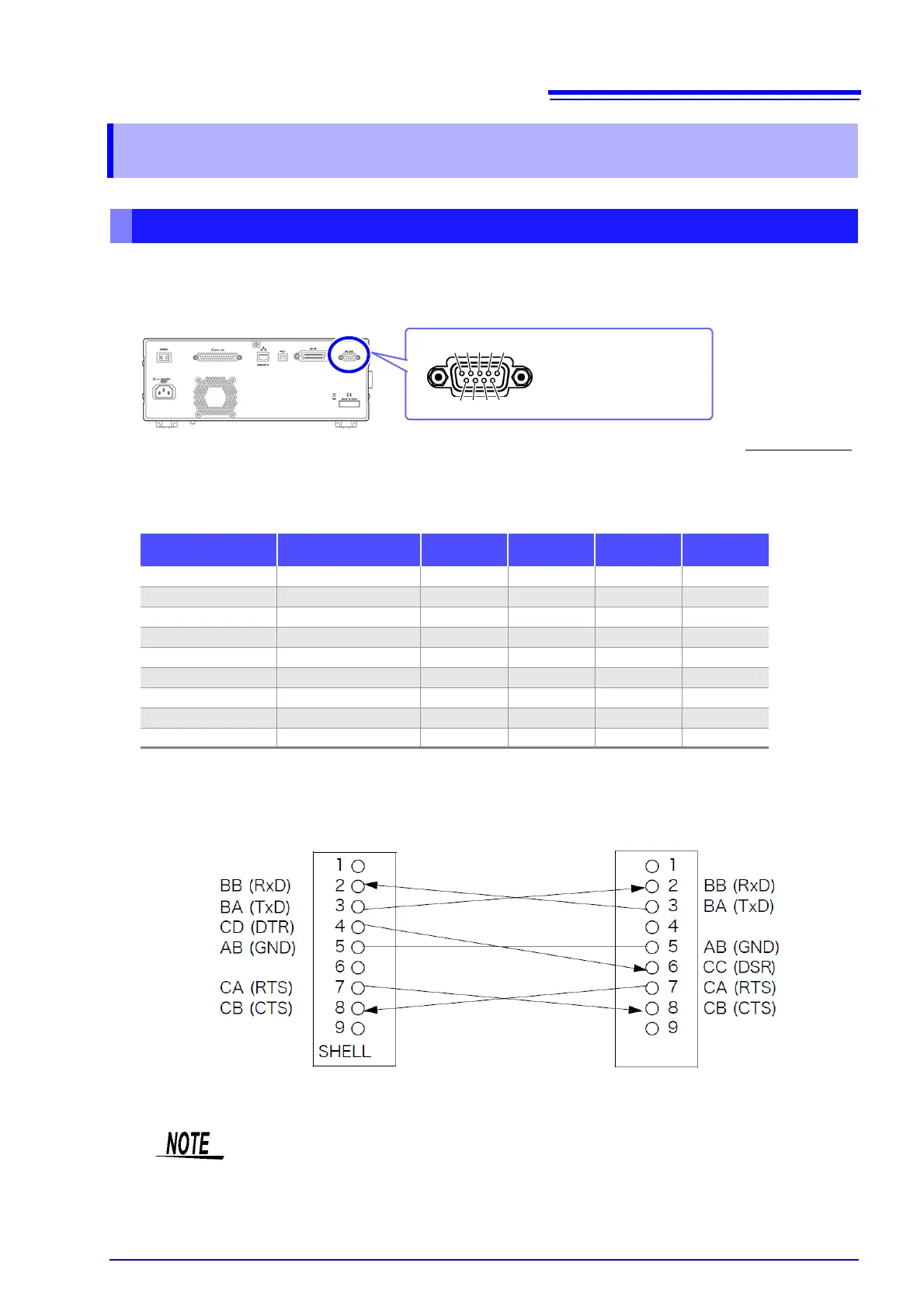
Connect the RS-232C cable to the RS-232C connector.
(Recommended cable: 9637 RS-232C cable)
Example: Connecting to a DOS/V PC
Specification: D-sub 9-pin female and female connector, reverse connection
2.2 RS-232C Connection and Settings
Connecting the RS-232C Cable
Male 9-pin D-sub
#4-40 attaching screws
To connect the instrument to a controller (DTE), use a crossover cable
compatible with the connectors on both the instrument and the controller.
The I/O connector is a DTE (Data Terminal Equipment) configuration.
6 7 8 9
1 2 3 4 5
Connector (D-sub)
Pin No.
Interchange Circuit
Name
CCITT
Circuit No.
EIA
Abbreviation
JIS
Abbreviation
Common
Abbreviation
1Unused
2 Received Data 104 BB RD RxD
3 Transmitted Data 103 BA SD TxD
4 Data Terminal Ready 108/2 CD ER DTR
5 Signal Ground 102 AB SG GND
6 Unused
7 Request to Send 105 CA RS RTS
8 Clear to Send 106 CB CS CTS
9Unused
Hardware control will not work properly if you use a cable that has CA(RTS) and CB(CTS)
short-circuited.