EasyManua.ls Logo

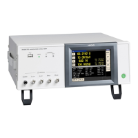
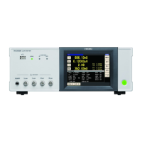
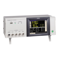
Hioki IM3570 User Manual

Hioki IM3570
458 pages
To Next Page IconTo Next Page
Page #1 background imageLoading...
Page #1 background image
IM3570
Instruction Manual
IMPEDANCE ANALYZER
EN
Dec. 2018 Revised edition 8
IM3570A981-08 18-12H

Table of Contents

Other manuals for Hioki IM3570

Questions and Answers:

Hioki IM3570 Specifications

General IconGeneral
BrandHioki
ModelIM3570
CategoryMeasuring Instruments
LanguageEnglish

Summary

Chapter 1 Overview

1.1 Product Overview Features

Details the key features, capabilities, and applications of the HIOKI IM3570 Impedance Analyzer.

1.2 Names and Functions of Parts

Identifies and explains the function of each part and connector on the front, rear, and sides of the IM3570 instrument.

1.3 Screen Configuration and Operation

Explains the instrument's screen layout, touch panel operation, and navigation for various settings.

Chapter 2 Measurement Preparations

2.1 Preparation Flowchart

Provides a step-by-step flowchart for preparing the IM3570 impedance analyzer for measurement.

2.2 Pre-Operation Inspection

Details the essential checks of the instrument and cables before operation to ensure safety and accuracy.

2.3 Connecting the Power Cord

Instructs on safely connecting the power cord to the instrument and powering it on.

2.4 Connecting the Measurement Cables, Probes, or Fixture

Explains the proper connection of measurement cables, probes, and fixtures to the instrument terminals.

2.5 Turning the Power On and Off

Describes the procedure for powering the instrument on and off, including standby mode operation.

Chapter 3 Measurement Example

3.1 When LCR Measurement Mode

Demonstrates a practical measurement example for LCR mode, specifically measuring a laminated ceramic capacitor.

3.2 When Analyzer Measurement Mode

Provides a practical measurement example for analyzer mode, focusing on measuring an element with resonance points.

Chapter 4 LCR Function

4.1 About LCR function

Explains the LCR function's capability to measure impedance, phase angle, and other parameters of circuit components.

4.2 Setting Basic Settings of Measurement Conditions

Guides users on setting fundamental measurement conditions like frequency, signal level, and range in LCR mode.

4.3 Setting DC Resistance Measurement

Details the process of setting up DC resistance measurements, including signal level and range configurations.

4.4 Judging Measurement Results

Explains how to evaluate measurement results using comparator and BIN measurement for quality assessment.

Chapter 5 ANALYZER Function

5.1 About ANALYZER function

Introduces the analyzer function for performing sweep measurements of frequency and signal level with graphical results.

5.2 Setting Basic Settings of Measurement

Covers configuring basic measurement settings for analyzer mode, including sweep parameters and trigger configurations.

5.3 Normal Sweep

Explains how to set sweep range and number of points for performing normal sweep measurements.

5.4 Segment Sweep

Details setting up and performing sweep measurements across multiple segments with individual parameter configurations.

5.5 Setting the Graph Display Method

Guides on configuring graph display settings such as horizontal axis, vertical axis, and grid display.

5.6 Checking the Measurement Values

Explains how to use cursors and search functions to examine measurement values at specific points.

5.7 Judging Measurement Results (Comparator Function)

Describes how to set judgment areas and criteria for evaluating measurement results using comparator functions.

5.8 Editing Judgment Points

Explains how to edit judgment points and set upper/lower limit values for comparator measurements.

5.9 Application Settings

Covers advanced settings like saving results, error detection, and I/O configurations for analyzer mode.

5.10 Equivalent Circuit Analysis Function

Details the use of the optional IM9000 firmware for analyzing equivalent circuits and simulating frequency characteristics.

Chapter 6 Continuous Measurement Function

6.1 Initial Screen

Provides an overview of the initial screen for continuous measurement, including panel selection and operation keys.

6.2 Setting Continuous Measurement

Guides on selecting and setting panels for continuous measurement, requiring prior saving of conditions.

6.3 Performing Continuous Measurement

Explains the procedure for executing continuous measurements, including starting and stopping the process.

6.4 Checking the Continuous Measurement Results

Describes how to check and analyze the results obtained from continuous measurements.

6.5 Setting Application Settings

Covers application settings specific to continuous measurement, such as display timing, trigger, and halt conditions.

Chapter 7 Error Compensation

7.1 Setting Open Circuit Compensation

Explains how to compensate for measurement errors caused by open circuits in test cables or fixtures.

7.2 Short Circuit Compensation

Details how to compensate for errors caused by short circuits in test cables or fixtures.

7.3 Compensating Values to Match Reference Values (Load Compensation)

Describes how to perform load compensation by measuring a reference sample to match values.

7.4 Compensating Measurement Cable Errors (Cable Length Compensation)

Explains how to reduce measurement errors influenced by cable length by setting the compensation value.

7.5 Calculating Values Scaling

Guides on applying a compensation function to measurement values by setting scaling coefficients.

Chapter 8 Setting the SYSTEM

8.1 Setting the Interface

Details how to configure the instrument's interface settings for computer control and printer connection.

8.2 Checking the Version of the Instrument

Explains how to check the instrument's software version and the status of optional firmware.

8.3 Self Checks (Self Diagnosis)

Covers performing self-checks like panel, screen, ROM/RAM, and I/O tests for instrument verification.

8.4 Setting the Date and Time

Provides instructions for setting the instrument's internal date and time for accurate data management.

Chapter 9 Saving and Loading Panel Information

9.1 Saving Measurement Conditions (Panel Save Function)

Explains how to save measurement conditions and compensation values as a panel to the instrument or USB drive.

9.2 Loading Measurement Conditions (Panel Load Function)

Guides on loading saved measurement conditions and compensation values from the instrument or USB drive.

9.3 Changing a Panel Name

Details how to rename saved panels for better organization and management.

9.4 Deleting a Panel

Explains the procedure for deleting saved panels from the instrument's storage.

Chapter 10 Using USB Flash Drive

10.1 Inserting and Removing USB flash drive

Provides instructions on safely inserting and removing USB flash drives from the instrument's USB port.

10.2 About the File Operation Screen

Explains the file list screen and operations like creating folders and deleting files.

10.3 About the File Save Setting Screen

Details configuration settings for file saving, including format, destination, and text options.

10.4 Saving Measurement Data

Explains how to save measurement data, screen copies, and instrument settings to a USB drive.

10.5 Loading Measurement Data

Guides on loading measurement data from USB for graph display or equivalent circuit analysis.

10.6 Saving Instrument Settings

Explains how to save instrument settings, including panel information, to a USB flash drive.

10.7 Reading Setting Conditions

Describes how to load saved setting files or panel files from a USB drive to restore instrument configurations.

10.8 File and Folder Operations

Covers operations for managing files and folders on a USB flash drive, including formatting and deletion.

Chapter 11 External Control

11.1 External Input/Output Connector and Signals

Details the EXT I/O connector, signal descriptions, and safety precautions for external control.

11.2 Timing Chart

Provides timing charts for LCR, analyzer, and continuous measurement modes illustrating signal sequences.

11.3 Internal Circuitry

Illustrates the instrument's internal circuitry, including input/output circuits and connection examples.

11.4 External I/O Settings

Explains settings for external I/O, including delay times, trigger logic, and EOM output configurations.

11.5 External Control Q&A

Addresses common questions regarding external trigger input, signal issues, and computer control.

11.6 Measurement Using a Computer

Describes how to control the instrument remotely using communication commands from a computer.

Chapter 12 Printing

12.1 Connecting the Printer

Provides instructions on connecting a compatible printer and lists the necessary printer requirements.

12.2 Instrument and Printer Settings

Details the instrument and printer settings required for successful printing operations.

12.3 Printing

Explains the printing process, including auto and manual methods, and shows example printouts.

Chapter 13 Specifications

13.1 General Specifications

Lists the general specifications of the IM3570, covering measurement modes, items, ranges, and output impedance.

13.2 Measurement Range and Accuracy

Provides detailed tables for measurement ranges, guaranteed accuracy, and accuracy coefficients.

13.3 About Measurement Times and Measurement Speed

Explains how measurement times vary based on conditions and lists measurement speed and wait time coefficients.

Chapter 14 Maintenance and Service

14.1 Inspection, Repair and Cleaning

Covers inspection, repair warnings, and details on replaceable parts like capacitors and batteries.

14.2 Troubleshooting

Provides a guide to diagnosing and resolving common instrument issues with symptoms, causes, and remedies.

14.3 Error display

Lists and explains various error messages, their descriptions, and corresponding remedy actions.

14.4 Discarding the Instrument

Provides instructions for safely removing the lithium battery and disposing of the instrument.

Appendix 1 Measurement Parameters and Arithmetic Expressions

Appendix 2 Measurement of High Impedance Components

Appendix 3 Measurement of In-circuit Components

Appendix 4 Countermeasures Against Incorporation of External Noise

Appendix 4.1 Countermeasures Against Incorporation of Noise from the Power Line

Explains methods to reduce power line noise using grounding and noise filters.

Appendix 4.2 Countermeasures Against Noise from the measurement Cables

Details techniques to suppress noise from measurement cables using anti-interference ferrite cores.

Appendix 5 Supplying DC Bias

Appendix 5.1 How to Supply a DC Bias Voltage

Explains how to apply DC voltage bias to test samples using an external circuit.

Appendix 5.2 How to Supply a DC Bias Current

Details how to apply DC current bias to samples like transformers or choke coils using an external circuit.

Appendix 6 The Residual Charge Protection Function

Appendix 7 Series Equivalent Circuit Mode and Parallel Equivalent Circuit Mode

Appendix 8 Selecting the Equivalent Circuit Model

Appendix 9 Open Circuit Compensation and Short Circuit Compensation

Appendix 10 Rack Mounting

Appendix 11 Dimensional Diagram

Appendix 12 Initial Settings Table

Appendix 13 Device Compliance Statement

Related product manuals