3.1 When LCR Measurement Mode
33
3
Chapter 3 Measurement Example
The following shows measurement examples of the LCR measurement mode and analyzer measurement mode.
Necessary items: 9263 SMD test fixture
Laminated ceramic capacity you want to measure
Measurement
Example Chapter 3
3.1 When LCR Measurement Mode
Measuring a Laminated Ceramic Capacitor
1
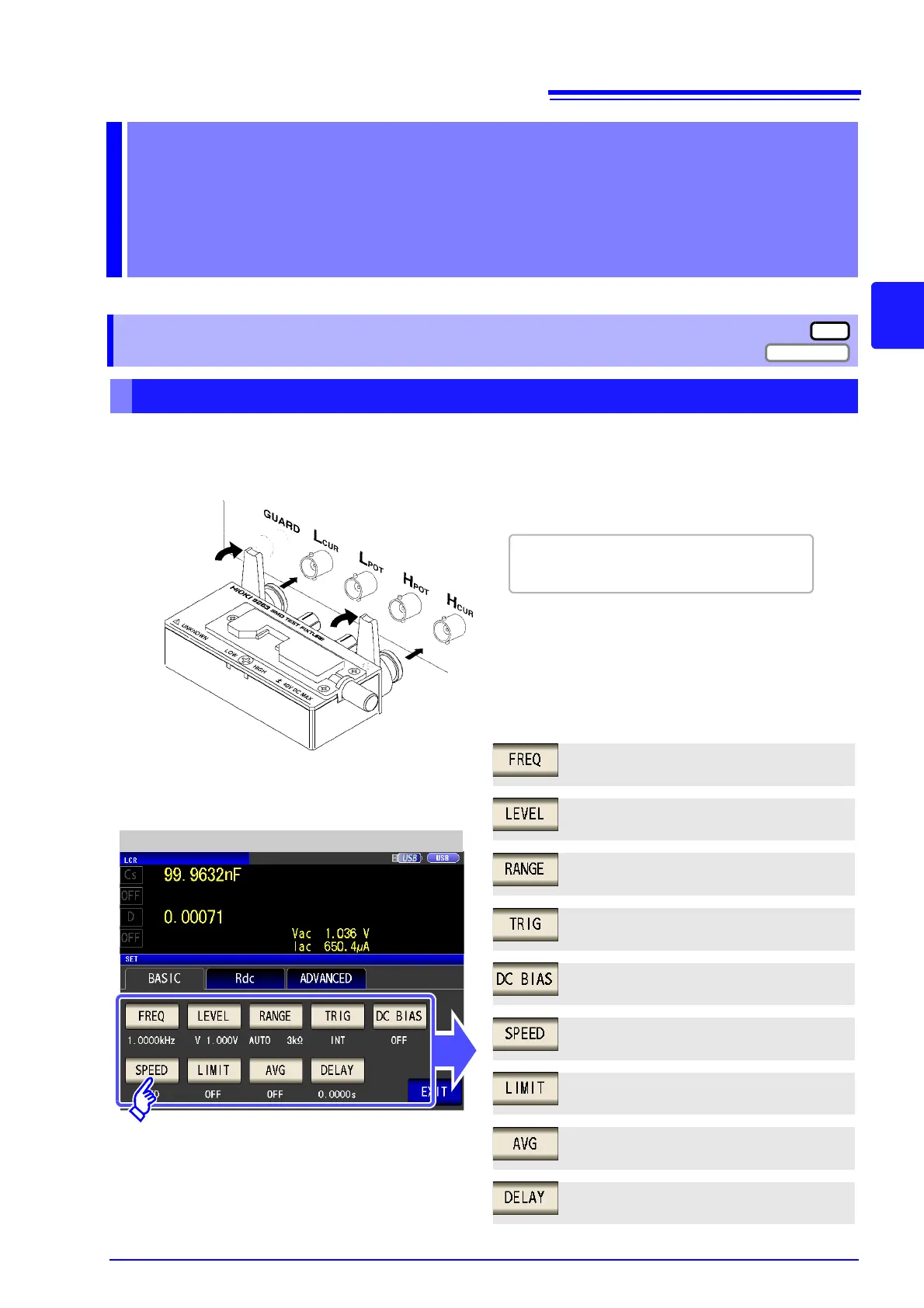
Connect the 9263 SMD test fixture to the measurement terminals.
For the connection procedure, refer to the
instruction manual supplied with the fixture.
2
Set the measurement conditions.
Select the item you want to set, and set it as
follows.
LCR Basic Settings
Measurement frequency: 1 kHz(p. 41)
Measurement signal level: 1 V (p. 43)
Measurement range: AUTO (p. 49)
Measurement speed: MED(p. 59)
Voltage and current limit: (p. 60)
Average: OFF (p. 62)
Trigger delay: 0 s (p. 64)
Trigger: INT(p. 55)
DC bias: OFF (p. 57)