Appendix 3 Measurement of In-circuit Components
A4
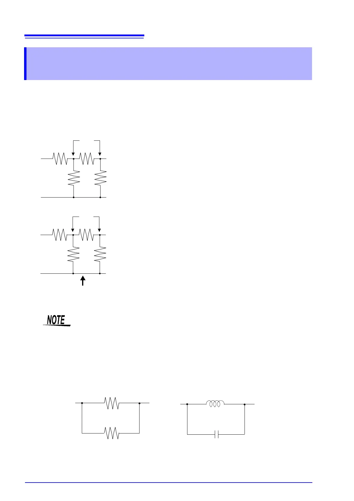
Measure an in-circuit component after providing guarding.
Referring to the following figure, when measuring a resistance value
for the resistor
R
2
, even if the tips of the two probes are contacted
against the ends of the resistor
R
2
, considering the sum of the cur-
rent flowing through the resistor
R
2
and the current flowing through
the resistors
R
3
and R
4
, what is obtained is the resistance value for
the parallel combination:
If as shown in the next figure a guard terminal is used, the current
flowing through the resistors
R
3
(not flowing through R
4
) is absorbed
by this guard terminal, so that the resistance value for the resistor
R
2
is accurately measured.
Appendix 3 Measurement of In-circuit
Components
RR
2
R
3
R
4
+
R
2
R
3
R
4
++
----------------------------------
=
R
4
R
3
R
2
R
1
HL
• The accuracy of measurement will not be improved in cases where for example R
2
>> R
3
and R
3
is close to zero.
• Individual elements cannot be isolated and measured separately in compound circuits
consisting of the same element, for example two resistors as shown in the diagram.
However, individual elements can be isolated and measured separately in compound cir-
cuits such as an inductor and capacitor by using the IM9000 Equivalent Circuit Analysis
Firmware (option).
Isolated measurement is supported for five equivalent circuit models.
See "5.10.1 About the Equivalent Circuit Analysis Function" (p. 238)
Two resistors in parallel
Coil and capacitor in parallel