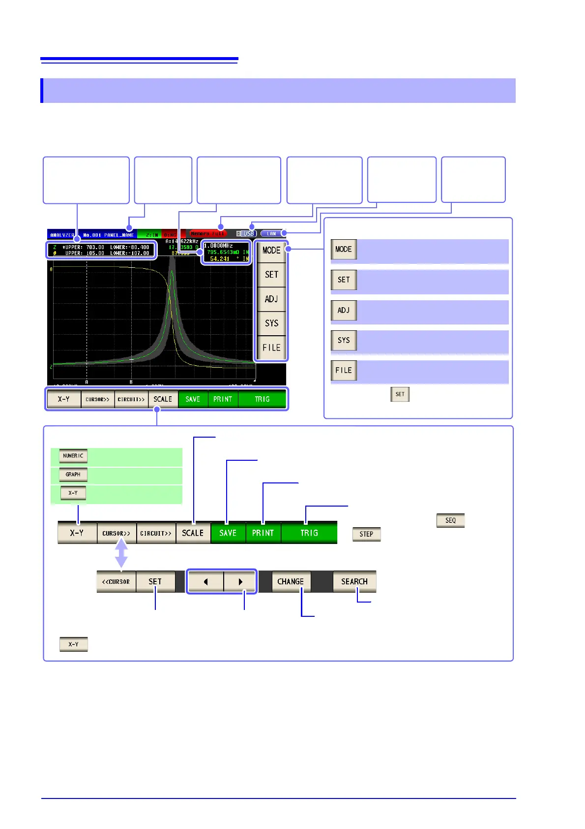
Measurement starts. (p. 137)
(This is displayed when or
is selected for the trigger setting.)
Perform a search. (p. 190)
The settings of differ depending on the
measurement mode.
Menu keys
Select the measurement mode.(p. 13)
Set the details.(p. 133)
Set the compensation.(p. 273)
Set the system.(p. 305)
Set the save settings.(p. 329)
Select the screen display method.
Displays list of numeric
values.
Displays graph.
Displays an X-Y graph.*
(p. 263)
Indicates the maximum
and minimum values of
the vertical axis of the
graph.
Indicates the usage
status of internal
memory. (p. 106)
Print the screen. (p. 381)
Save the screen. (p. 333)
Set the vertical axis to auto scale. (p. 185)
Indicates that a
USB flash drive is
connected.
(p. 329)
Indicates the
interface that is
currently set.
Indicates the mea-
surement value of the
point currently being
measured.
Indicates the
name of the
loaded panel.
The setting of the cursor.
(p. 188)
Move the cursor.
(p. 188)
Switch measured values and simulation values
during equivalent circuit analysis.
* is displayed only when the IM9000 Equivalent Circuit Analysis Firmware has been installed.