11.1 External Input/Output Connector and Signals
367
11
Chapter 11 External Control
You can select rising or falling for the valid edge of a trigger.
See "Enabling Trigger Input for during Measurement and Setting the Valid Edge of Trigger Input" (p. 117), (p. 228)
Signal Descriptions
TRIG
• When the trigger setting is the external trigger , measurement is performed
once with the falling (ON) or rising (OFF) edge of the TRIG signal. The edge direction
can be set in the setting screen. (Initial value: Falling (ON))
See: "Enabling Trigger Input for during Measurement and Setting the Valid Edge of Trig-
ger Input" (p. 117), (p. 228)
• When the trigger source is set to the internal trigger , trigger measurement is
not performed.
• You can set whether to enable or disable TRIG signal input during measurement (during
output of the EOM signal (HI)).
See: "Enabling Trigger Input for during Measurement and Setting the Valid Edge of Trig-
ger Input" (p. 117), (p. 228)
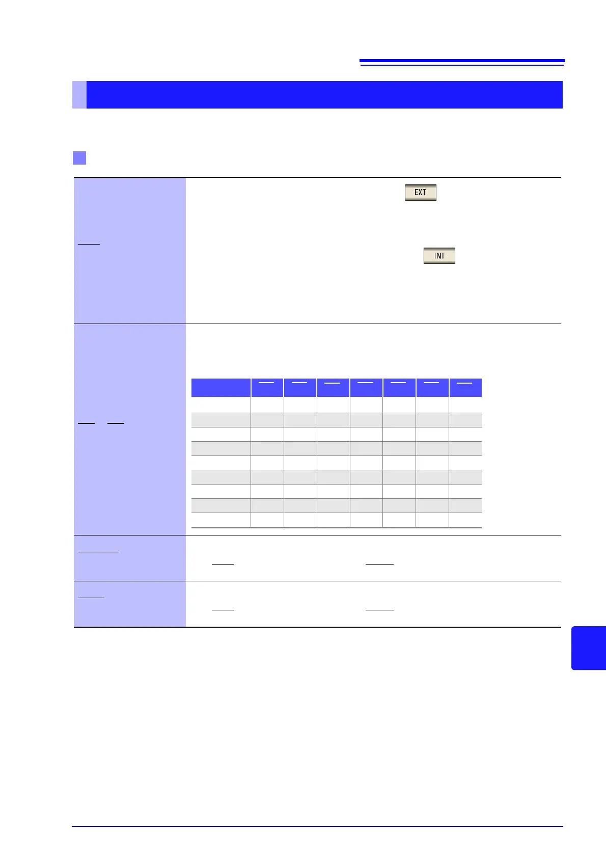
LD0 to LD6
Selects the number of the panel to load.
If a trigger signal is input in external trigger mode, the selected panel is loaded and used for
measurement.(p. 377)
LD-VALID
Inputs a negative logic signal from an external device so that the selected panel number is
recognized as valid.
After TRIG
input, maintain a Low level until INDEX is outputted.
CALIB
When the DC adjustment function for during DC resistance measurement is set to OFF, the
offset value generated in the internal circuit can be obtained at the desired timing.
After TRIG
input, maintain a Low level until INDEX is outputted.
PIN No. LD6 LD5
LD4
LD3 LD2 LD1
LD0
Panel 1 0 0 0 0 0 0 1
Panel 2 0 0 0 0 0 1 0
Panel 4 0 0 0 0 1 0 0
Panel 8 0 0 0 1 0 0 0
Panel 16 0 0 1 0 0 0 0
Panel 32 0 1 0 0 0 0 0
Panel 64 1 0 0 0 0 0 0
Panel 127 1 1 1 1 1 1 1
Panel128 0 0 0 0 0 0 0
0: (HIGH: 5 V to 24 V), 1: (LOW: 0 V to 0.9 V)