Appendix
Appendix 7 Series Equivalent Circuit Mode and Parallel Equivalent Circuit Mode
A11
The instrument measures the current flowing to the test sample and the voltage at both ends of the test sam-
ple, and determines Z and . Other measurement items such as L, C, and R are calculated from Z and . At
this time, the mode for calculation becomes series equivalent circuit mode if the resistance components for C
(or L) are assumed to be in series, and the mode becomes parallel equivalent circuit mode if the resistance
components for C (or L) are assumed to be in parallel. It is, therefore, necessary to select the correct equiva-
lent circuit mode to reduce errors because the calculation expression differs for series equivalent circuit mode
and parallel equivalent circuit mode.
Generally, for measurement of a low impedance device (approx. less than 100 ) like a large capacitance
capacitor or a low inductance, a seriesequivalent circuit mode will be selected. While, for a high impedance
device (approx. more than 10 k) like a small capacitance capacitor or a high inductance, a parallel-equiva-
lent circuit mode will be selected. When you are not sure about selection of circuit mode, please ask the parts
maker. (ex. a impedance approx. between 100 and 10 k)
Appendix 7 Series Equivalent Circuit Mode and
Parallel Equivalent Circuit Mode
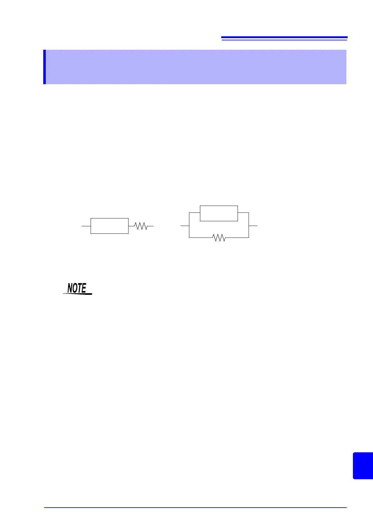
Series equivalent circuit Parallel equivalent circuit
C (or L)
C (or L)
Because measurement value in each equivalent circuit mode is obtained through calcula-
tion, measurement values of both modes can be displayed. However, please note that the
appropriate equivalent circuit depends on the test sample.