Procedure
2
3
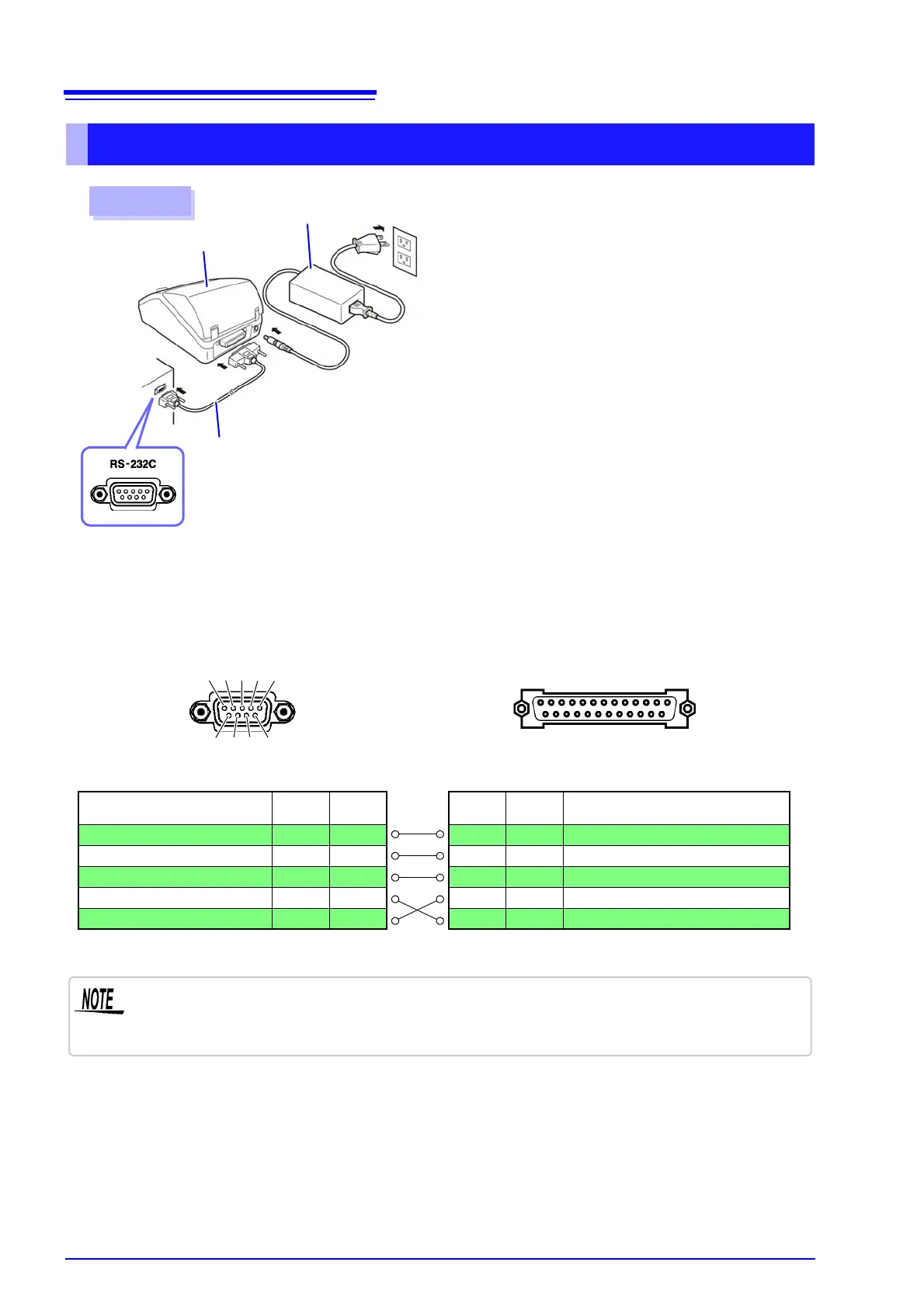
Printer
AC Adapter
RS-232C Cable
25 ....................... 14
Printer (25-pin) Connector
IM3570 (9-pin) Connector
Pin
Signal
Name
Function
2 TxD
Transmit Data
3 RxD
Receive Data
7 GND
Signal or Common Ground
4 RTS
Request to Send
5 CTS
Clear to Send
Function
Signal
Name
Pin
Receive Data
RxD 2
Transmit Data
TxD 3
Signal or Common Ground
GND 5
Request to Send
RTS 7
Clear to Send
CTS 8
6 7 8 9
1 2 3 4 5
Connector Pinouts
13 ....................... 1
1
Confirm that the instrument and printer are
turned off.
2
Connect the AC adapter to the printer, and insert
the power plug into an outlet.
3
Connect the RS-232C cable to the RS-232C con-
nectors on the instrument and printer.
4
Turn the instrument and printer on.
Rear
To use hardware flow control, you will need an RS-232C cable whose RTS and CTS wires are
connected (7-pin at instrument to 5-pin at printer or 8-pin at instrument to 4-pin at printer). Hard-
ware flow control cannot be used with cables whose RTS and CTS wires are shorted together.