Home
Hioki
Measuring Instruments
IM3570
Page 317 (9.1 Saving Measurement Conditions (Panel Save Function))
Hioki IM3570 - 9.1 Saving Measurement Conditions (Panel Save Function)
458 pages
Manual
Save Page as PDF
To Next Page
To Next Page
To Previous Page
To Previous Page
Loading...
8.3 Self Checks
(Self Diagnosis)
309
8
Chapter 8 Setting the SYSTEM
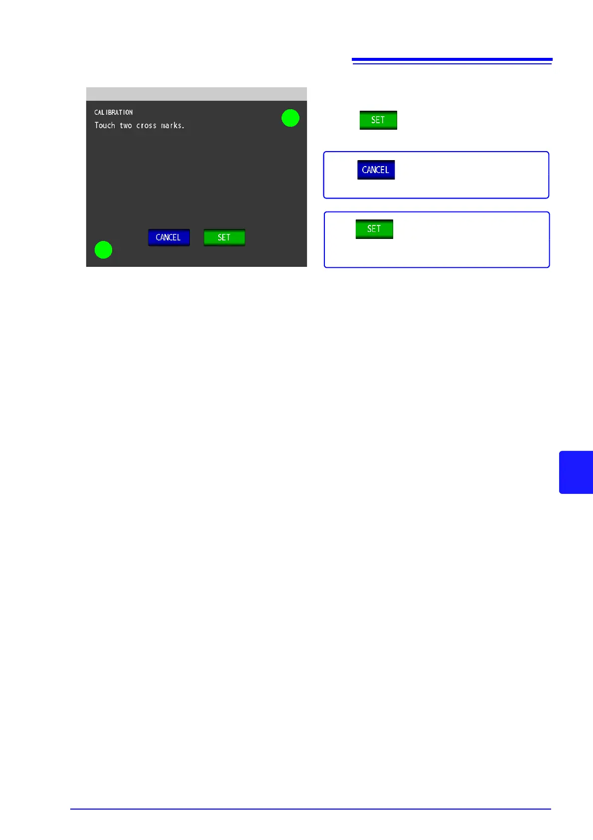
Press
to close the setting scree
n.
4
Panel Compensation
Complete
If the
indication does not appear, the instru-
ment needs to be repaired.
Contact your dealer or Hioki representative.
Press
to start panel calibration from the
beginni
ng.
316
318
Table of Contents
Main Page
Default Chapter
3
Table of Contents
3
Chapter 1 Overview
17
Product Overview Features
17
Names and Functions of Parts
18
Screen Configuration and Operation
20
Initial Screen
20
Measurement Mode Selection Screen
21
Advanced Settings Screen
22
Compensation Settings Screen
29
System Settings Screen
30
Save Settings Screen
32
Parameter Settings Screen
33
Chapter 2 Measurement Preparations
35
Preparation Flowchart
35
Pre-Operation Inspection
36
Connecting the Power Cord
37
Connecting the Measurement Cables, Probes, or Fixture
38
Turning the Power on and off
39
Chapter 3 Measurement
41
Example
41
When LCR Measurement Mode
41
When Analyzer Measurement Mode
43
Chapter 4 LCR Function
45
About LCR Function
45
Initial Screen
46
Setting Display Parameters
47
Setting Basic Settings of Measurement Conditions
49
Setting the Measurement Frequency
49
Setting the Measurement Signal Level
51
Setting the Measurement Range
57
Setting AUTO Ranging
57
Setting the Ranging to HOLD
59
Low Z High Accuracy Mode
61
Perform Measurements with User-Defined Timing (Trigger Measurement)
63
Setting the DC Bias
65
Setting the Measurement Speed
67
Setting the Voltage/Current Limit
68
Displaying Average Values (Averaging Set)
70
Measuring at Desired Time (Trigger Delay)
72
Setting DC Resistance Measurement
73
Setting the Measurement Signal Level
74
Setting the Measurement Range
77
Setting AUTO Ranging
77
Setting the Ranging to HOLD
79
Low Z High Accuracy Mode
81
Setting the DC Adjustment Function
83
Setting the Measurement Speed
85
Setting the Voltage/Current Limit
86
Displaying Average Values (Average Set)
88
Setting the Delay Time
90
Judging Measurement Results
92
Judging with Upper and Lower Limit Values(Comparator Measurement Mode)
94
Setting the Upper or Lower Limit Value as an
96
(Absolute Value Mode)
96
Setting the Upper or Lower Limit Value as a Percentage (%) Relative to a Reference Value (Percentage Mode)
97
Setting Upper and Lower Limit Values as ( %) Values Relative to the Offset from the Reference Value (Deviation Percentage Mode)
99
Classifying Measurement Results (bin Measurement)
101
Setting the Upper or Lower Limit Value as an
103
Setting the Upper or Lower Limit Value as a Percentage (%) Relative to a Reference Value (Percentage Mode)
106
Setting Upper and Lower Limit Values as
109
Reference Value
110
Setting Application Settings
112
Synchronizing Measurement (Trigger Synchronous Output Function)
112
Trigger Synchronous Output Function
113
Saving Measurement Results (Memory Function)
114
Detecting OPEN During 2-Terminal Measurement (HIGH-Z Reject Function)
116
Monitoring the Detection Level (Monitoring the Detection Level Function)
118
Monitoring the Detection Level Function
119
Setting the Delay Time from the Output of Comparator and bin Judgment Results until Output of EOM (LOW) and Resetting Judgment Results
123
Enabling Trigger Input for During Measurement and Setting the Valid Edge of Trigger Input
125
Setting the EOM Output Method
127
Disabling Key Operation (Key-Lock Function)
129
10Setting the Number of Display Digits
132
11Enlarging Display of Measurement Values
134
12Setting the LCD to ON/ off
135
13Setting Operation Sounds (Beep Sounds)
136
14Initializing (System Reset)
137
Chapter 5 ANALYZER
139
Function
139
About ANALYZER Function
139
Initial Screen
140
Setting Basic Settings of Measurement
141
Setting the Measurement Parameter
141
Setting the Sweep Parameter
143
Setting the Trigger
145
Setting the Display Timing
147
Setting the Trigger Delay
148
Segment Setting
150
Normal Sweep
151
Setting Sweep Points
151
Setting the Measurement Signal
165
Setting the Measurement Range
168
Setting the Measurement Range
172
Setting the Measurement Speed
172
Displaying as Average Values (Average Set)
173
Setting the Point Delay
174
Setting the DC Bias
175
Segment Sweep
177
Select Segments
177
Setting the Graph Display Method
184
Setting the Horizontal Axis
184
Overwrite Setting
184
Horizontal Axis Scale Setting
185
Span Setting
187
Setting the Vertical Axis
189
Draw Color Setting
189
Vertical Axis Scale Setting
191
Setting Grid Display
194
Checking the Measurement Values
196
Setting the Cursor
196
Cursor Display Setting
197
Cursor Move Setting
197
Cursor Move Setting
198
Search Function Setting
198
Search Target Parameter Setting
199
Option Setting
199
Auto Search Setting
200
Moving the Cursor
201
Performing Measurement Value Search
202
Judging Measurement Results (Comparator Function)
205
Area Judgment
205
Peak Judgment
216
Editing Judgment Points
225
Application Settings
227
Saving Measurement Results (Memory Function)
227
Detecting OPEN During 2-Terminal Measurement (HIGH-Z Reject Function)
230
Setting the Detection Sensitivity for
232
(Overflow or Underflow)
232
Setting the Delay Time from the Output of Comparator Judgment Results until Output of EOM (LOW) and Resetting Judgment Results
234
Enabling Trigger Input for During Measurement and Setting the Valid Edge of Trigger Input
236
Setting the EOM Output Method
237
Disabling Key Operation (Key-Lock Function)
238
Setting the LCD to ON/ off
241
Setting Operation Sounds (Beep Sounds)
242
Synchronous Output Function)
243
11Initializing (System Reset)
245
Equivalent Circuit Analysis Function
246
Function
246
2Configuring Basic Settings for Analysis
247
Setting the Equivalent Circuit Model
247
Setting the Method of Analysis
249
Setting the Frequency Range to Analyze
251
Selecting the Segment to Analyze
253
Configuring Calculation of the Electromechanical Coupling Coefficient (K)
255
Setting the Position at Which to Display Analysis Results
258
3Performing Equivalent Circuit Analysis
260
Performing Frequency Sweep Measurement
260
Performing Equivalent Circuit Analysis
261
4Simulating Frequency Characteristics
266
5Judging Analysis Results
268
Setting the Upper or Lower Limit Value
268
Making Judgments Using Analysis Results
270
6Generating X-Y Displays
271
Creating an X-Y Display
271
Chapter 6 Continuous Measurement Function
273
Initial Screen
273
Setting Continuous Measurement
274
Performing Continuous Measurement
275
Checking the Continuous Measurement Results
276
Setting Application Settings
277
Setting the Display Timing
277
Setting the Trigger
278
Halting Continuous Measurement at a FAIL Judgment Result
279
Setting the LCD to ON/ off
280
Chapter 7 Error Compensation
281
Setting Open Circuit Compensation
281
All Compensation
282
Spot Compensation
285
Short Circuit Compensation
288
All Compensation
290
Spot Compensation
293
Compensating Values to Match Reference Values (Load Compensation)
296
7.3 Compensating Values to Match
297
7.3 Compensating Values to Match
298
7.3 Compensating Values to Match
299
7.3 Compensating Values to Match
300
7.3 Compensating Values to Match
301
7.3 Compensating Values to Match
302
7.3 Compensating Values to Match
303
7.3 Compensating Values to Match
304
7.3 Compensating Values to Match
305
7.3 Compensating Values to Match
306
7.3 Compensating Values to Match
307
7.3 Compensating Values to Match
308
Compensating Measurement Cable Errors (Cable Length Compensation)
309
Calculating Values Scaling
310
Chapter 8 Setting the SYSTEM
313
Setting the Interface
313
Checking the Version of the Instrument
314
Self Checks (Self Diagnosis)
315
Setting the Date and Time
322
Chapter 9 Saving and Loading Panel Information
323
Saving Measurement Conditions (Panel Save Function)
325
Loading Measurement Conditions (Panel Load Function)
330
Changing a Panel Name
332
Deleting a Panel
334
Chapter 10 Using USB Flash Drive
337
Inserting and Removing USB Flash Drive
338
About the File Operation Screen
339
About the File Save Setting Screen
340
Saving Measurement Data
341
Saving a Copy of the Screen
349
Checking the Contents of Files
351
Changing the Save Folder
352
Loading Measurement Data
354
Saving Instrument Settings
357
Saving Instrument Settings
359
Saving All Settings of Instrument (ALL SAVE Function)
359
Reading Setting Conditions
363
Loading All Settings Saved on a USB Flash Drive (ALL LOAD Function)
363
File and Folder Operations
365
Formatting a USB Flash Drive
365
Deleting Files and Folders
367
Displaying the USB Flash Drive Information
370
Drive
337
Chapter 11 External Control
371
External Input/Output Connector and Signals
371
Connector Type and Signal Pinouts
372
Signal Descriptions
375
Timing Chart
377
1LCR Measurement
377
2Analyzer Measurement
380
(Sequential Operation)
381
(Step Operation)
383
Electrical Specifications
385
Internal Circuitry
386
Connection Examples
386
External I/O Settings
387
Setting Reset of Judgment Results
387
Enabling Trigger Input for During Measurement
387
Setting Valid Edge of Trigger Input
387
External Control Q&A
388
Measurement Using a Computer
388
Chapter 12 Printing
389
Connecting the Printer
389
Connecting the Printer to the Instrument
390
Instrument and Printer Settings
391
Make Instrument Settings
391
Printing
392
Chapter 13 Specifications
395
General Specifications
395
Measurement Range and Accuracy
403
About Measurement Times and Measurement Speed
407
Chapter 14 Maintenance and Service
411
Inspection, Repair and Cleaning
411
Troubleshooting
413
Error Display
415
Discarding the Instrument
417
Appendix
419
Appendix 1 Measurement Parameters and Arithmetic Expressions
419
Appendix 2 Measurement of High Impedance
421
Components
421
Appendix 3 Measurement of In-Circuit Components
422
Appendix 4 Countermeasures against
423
Appendix 5 Supplying DC Bias
425
Appendix 6 the Residual Charge Protection Function
428
Appendix 7 Series Equivalent Circuit Mode and Parallel Equivalent Circuit Mode
429
Appendix 8 Selecting the Equivalent Circuit Model
430
Appendix 9 Open Circuit Compensation and Short Circuit Compensation
431
Appendix 10Rack Mounting
432
Appendix 11Dimensional Diagram
434
Appendix 12Initial Settings Table
435
Appendix 13Device Compliance Statement
441
Other manuals for Hioki IM3570
Communication Instruction Manual
74 pages
Related product manuals
Hioki IM3523
74 pages
Hioki IM3536
276 pages
Hioki IM3533
400 pages
Hioki IM3523A
76 pages
Hioki IM3533-01
74 pages
Hioki IM7580A Series
21 pages
Hioki 3151
54 pages
Hioki 3197
200 pages
Hioki 3390
204 pages
Hioki PQ3100
242 pages
Hioki CM4371
72 pages
Hioki 3280-10F
104 pages