A
Ann WardSep 12, 2025
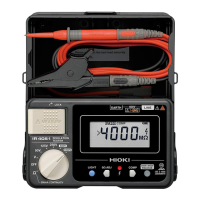
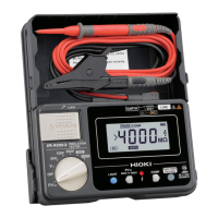
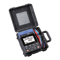
Why does my Hioki Test Equipment show the maximum display value?
- SsandersmichelleSep 12, 2025
This issue can occur if there is a broken connection in a test lead or if the test leads are not securely connected. Check the continuity of the test lead with a tester. Also, check the connection between the test leads and the instrument, and check the connection of the tips of the test leads.