MACH 100
Release
07/09
31
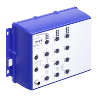
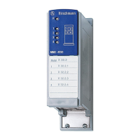
Figure 21: MACH 100 display elements
1 - Displays for device state
2 - Displays for port state
3 - Displays for port state, media module 1
4 - Displays for port state, media module 2
Device state
These LEDs provide information about conditions which affect the opera-
tion of the whole device.
If the manual adjustment is active on the “FAULT” signal contact, then the
detected error display is independent of the setting of the signal contact.
P - Power
(green/yellow LED)
Glowing green MACH 102-8TP, MACH 102-8TP-F, MACH 102-24TP-F:
Supply voltage is on.
MACH 102-8TP-R, MACH 102-8TP-FR, MACH 102-24TP-FR:
Supply voltages 1 and 2 are on.
Glowing yellow MACH 102-8TP-R, MACH 102-8TP-FR, MACH 102-24TP-FR:
Supply voltage 1 or 2 is on.
Not glowing MACH 102-8TP, MACH 102-8TP-F, MACH 102-24TP-F:
Supply voltage is below minimum value.
MACH 102-8TP-R, MACH 102-8TP-FR, MACH 102-24TP-FR:
Supply voltages 1 and 2 are below minimum value.
RM - Ring Manager (green/yellow LED)
Glowing green RM function active, redundant port disabled
Glowing yellow RM function active, redundant port enabled
Not glowing RM function not active
Flashing green Incorrect configuration of the HIPER-Ring (e.g. the ring is not
connected to the ring port).
Stand-by - Stand-by mode (green LED)
Glowing green Stand-by mode enabled.
Not glowing No stand-by mode.
FAULT - signal contact
(red LED)
Glowing red Signal contact 1 is open, i.e. it is reporting an error.
Not glowing Signal contact 1 is closed, i.e. it is not reporting an error.
RM and Stand-by - display saving processes of the AutoConfiguration Adapter (ACA)
Flashing alternately Error during saving process.
LEDs flash synchronously, two
times a second
Loading configuration from the ACA.
LEDs flash synchronously,
once a second
Saving the configuration in the ACA.
1
3
LS DA
USB
V.24
MACH 1000
2
1
LS DA
3
4
9
10
P
StandByRM
FAULT
R1
R2
5
6
7
8
13
14
11
12
17
18
15
16
21
22
19
20
25
26
23
24
LS DA
LS DA
LS DA
LS DA
2 4