41
5. INSTALLING AND PIPING THE DSP [Piping the DSP Air Compressor]
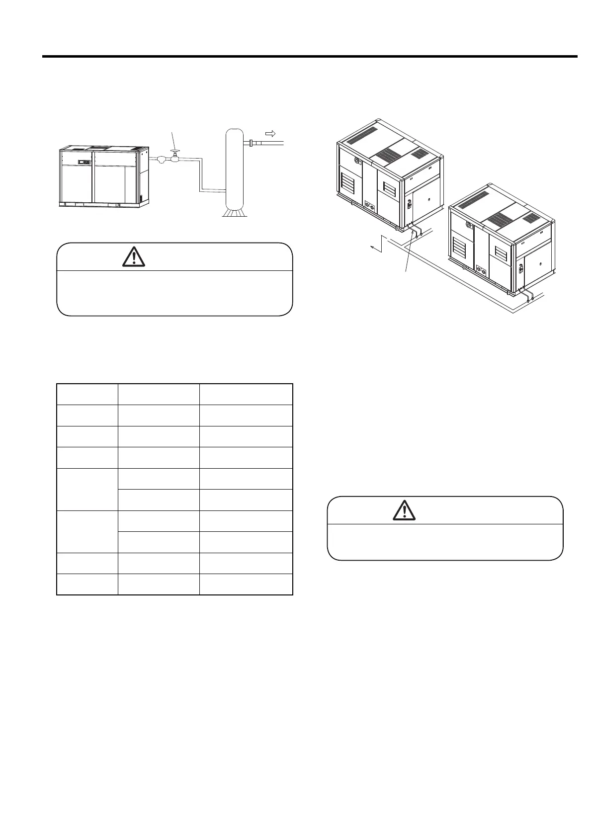
① As the DSP employs a 0%- or 100%-capacity, 2-step
capacity control system, install an air receiver tank on
the plan airline pipe. Its capacity is as indicated in the
following table.
5.4.5 Air Receiver Tank
Discharge
Air
Stop Valve
Air Receiver Tank
Model
Dis.Pressure (MPa)
[psi]
Minimum Capacity of Air
Receiver Tank (m
3
) [US gallon]
DSP-132WN
0.75/0.86/1.0
[110/125/145]
4.0 [1057]
DSP-145WN
0.75/0.86/1.0
[110/125/145]
4.0 [1057]
DSP-160WN
0.75/0.86/1.0
[110/125/145]
4.0 [1057]
DSP-200WN
0.75
[110]
4.5 [1190]
0.86/1.0
[125/145]
4.0 [1057]
DSP-240WN
0.75
[110]
5.0 [1320]
0.86/1.0
[125/145]
4.5 [1190]
DSP-160VWN
0.75/0.86/1.0
[110/125/145]
4.5 [1190]
DSP-240VWN
0.75/0.86/1.0
[110/125/145]
5.0 [1320]
If you fail to install an air receiver tank, the
DSP may load and unload frequently; its
mechanical service life may be shortened.
CAUTION
① Leave open the end of any condensate drain pipe.
② Do not merge the DSP’s condensate drain lines (for
the aftercooler, for intercooler, for the control line fil-
ter) into one. Also, do not merge any condensate drain
pipe into an external condensate drain pipe (for exam-
ple, one for other DSPs or one for an air receiver
tank). Otherwise, a pressure difference may be gener-
ated; as a result, the DSP cannot drain the condensate
or can drain it only abnormally or you cannot visually
check whether the condensate is regularly drained.
5.4.6 Condensate Drain Piping
Drain Pit
Drain Pipe
CAUTION
Un-drained condensate can backflow to the
DSP air compressor and cause it to fail.
② Do not install a check valve between the DSP and the
air receiver tank. Otherwise, the DSP may hunt, that
is, load and unload very frequently; the capacity con-
trol system may not work normally.
③However, in case of AUTO operation specification,
quantity control specification and alternate operation
specification, install air chambers of 4.5 m
3
(1190 US
gallon) or more for 132kW to 160kW and 5.0 m
3
(1320
US gallon) or more for 200kW to 240kW so as to max-
imize the energy saving effect.
④When selecting energy saving operation, install air
chambers of 4.5 m
3
(1190 US gallon) or more for
132kW to 160kW and 5.0 m
3
(1320 US gallon) or more
for 200kW to 240kW so as to maximize the energy
saving effect in all the areas of load factors .
 Loading...