59
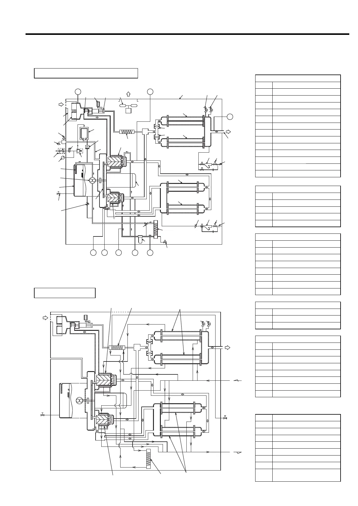
8. STANDARD COMPONENTS AND SUBSYSTEMS [Air/Oil Flow]
Intercooler
Oil Cooler
Blowoff air cooler
Suction
Aftercooler
1st-Stage Air-End
2nd-Stage Air-End
Cooling Water
Outlet
Cooling Water
inlet
Drain Valve
Compressed
Air Discharge
Flow Diagram
ir Intake for a
Compressor
Compressed
Air Discharge
PS4
TH3 TH5
2
3
4
5
10
21
22
23
24
38
53
52 9 9
8
7
7
8
PS2
PS1 TH2
1
31
32
35
34
36
33
25
6
6
15
14
1312
15
14
13
61
68
37
64
63
65
62
67
66
TH4
51
38
63SV
Exhaust
Suction
Legend
Compressor Air Flow[⇨]
1 First-Stage Air-End
2 Second-Stage Air-End
3 Gear Case
4 Stepup Gear
5 Motor
6 Intercooler
7 Check Valve
8 Aftercooler
9 Safety Valve
10 Discharge Air Outlet
12 Check Valve
13 Y-type strainer
14 Solenoid Valve
15 Orifice
Legend of Sensors and Switches
Symbol
Description
PS2
Pressure Sensor (discharge air pressure)
PS4
Pressure Sensor (oil pressure)
PS1
Pressure Sensor (interstage pressure)
TH2
Temperature Sensor (2nd-stage in)
TH4
Temperature Sensor (1st-stage out)
TH3
Temperature Sensor (2nd-stage out)
TH5 Temperature Sensor (oil)
63SV
Pressure Differential Sensor
(For suction Filter clogging detection)
Capacity Control & Blowoff Air Flow
21 Air Intake Filter
22 Suction Throttle Valve
23 Blowoff Valve
24 Blowoff Silencer
25 Blowoff air cooler
Oil Flow[→]
31 Oil Strainer
32 Oil Pump
33 Relief Valve
34 Oil Filter
35 Oil Cooler
36
Oil Temperature Control Valve
37 Gear Case Vent Pipe
38 Oil Drain Valve
Cooling Air Flow and Enclosure
51 Ventilating Fan
52 Enclosure
53 Air Intake Duct
Oil Mist Remover (OMR) Flow
61 Element
62 Filter-integrated Regulator
63 Solenoid Valve
64 Ejector
65 Air Pressure Gauge
66 Relief Valve
67 Vacuum Indicator
68 Float Trap
Compressed Air Flow and Oil Flow
Cooling Water Flow
 Loading...