64
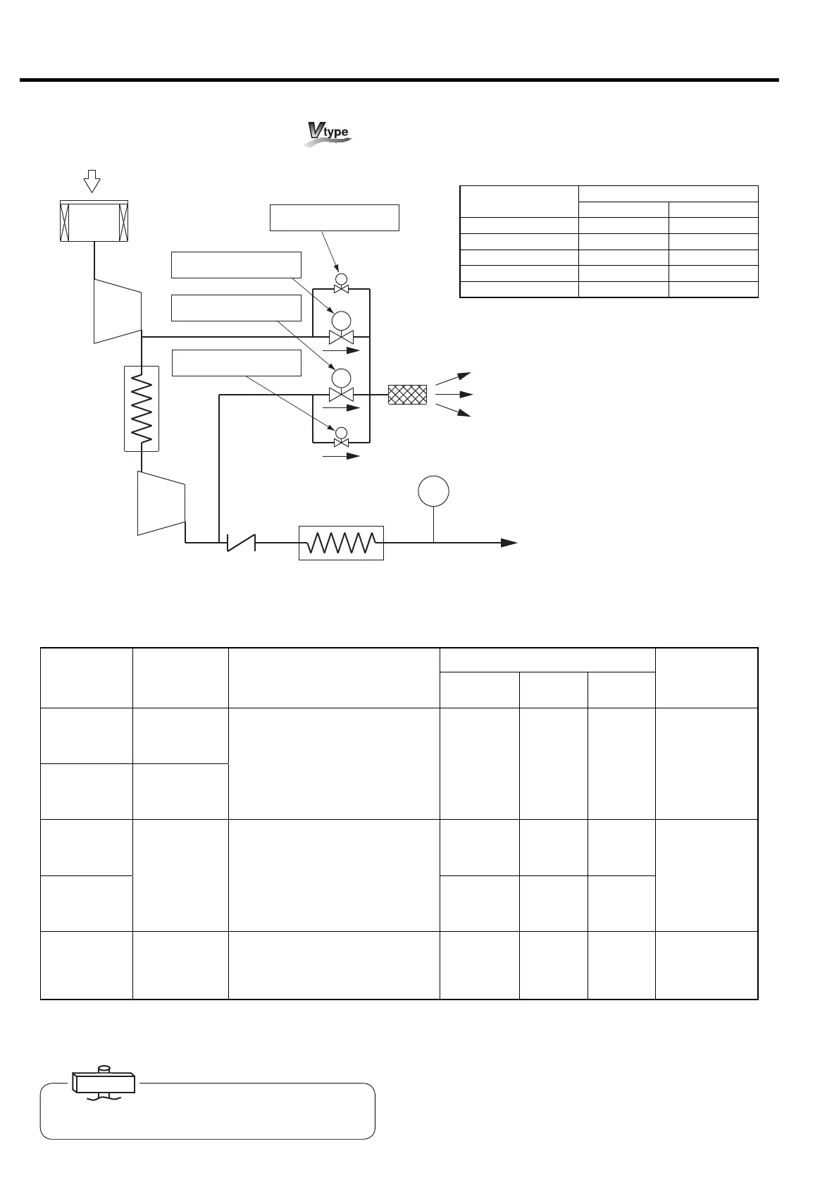
8. STANDARD COMPONENTS AND SUBSYSTEMS [Capacity Control System]
Air
Intake
Air Intake Filter
1st-Stage
ir End
Intercooler
Check Valve
Aftercooler
Blowoff
Silencer
Pressure
Sensor
Air
Discharge
1st-Stage
Blowoff Solenoid Valve (1)
2nd-Stage
Blowoff Solenoid Valve (1)
2nd-Stage
Blowoff Solenoid Valve (2)
1st-Stage
Blowoff Solenoid Valve (2)
2nd-Stage
Air End
PS2
8.4.3 Capacity Control System
8.4.4 Relation between Air Consumption Rate and Capacity Control System
※
Figure in
〔
〕
are for 0.93MPa models.
Air
Consumption
(%)
Operating
Frequency
(Hz)
Capacity Control System
Pressure Settings (MPa)
SW3
Settings
Setting
Items
Factory
Lower
Example
160VWN
100 to 60
[100 to 70]
160VWN
40 to 60
〔40 to 54〕
①
CPCS Motor Speed Control
Standard
0.75
〔0.93〕
0.65
〔0.83〕
AUTO ON
(INVA)
or
AUTO OFF
(INVB)
240VWN
100 to 55
[100 to 60]
240VWN
35 to 60
〔35 to 53〕
160VWN
60 to 5
[70 to 5]
24
〔24〕
②
Two-Step Purge
Start/Stop Control
Upper
(purge start)
0.77
〔0.95〕
0.75
〔0.93〕
AUTO ON
(INVA)
or
AUTO OFF
(INVB)
240VWN
55 to 5
[60 to 5]
Lower
(purge stop)
0.72
〔0.90〕
0.65
〔0.83〕
5 to 0
Motor
stopped
③
Motor Stop/Restart Control
(AUTO operation)
Lower
(motor restart)
0.72
〔0.90〕
0.65
〔0.83〕
AUTO ON
(INVA)
The DSP supports the 3 capacity control systems as above.
Depending on the varying air consumption, an appropriate system is automatically selected.
For more information, read the following page.
Flow of Purging Air and Action of Blowoff Solenoid Valve
Operation Phase
of DSP
Action of Blowoff Solenoid Valve
(1) (2)
Starting Opened fully Closed fully
Loading Closed fully Closed fully
Purging Opened fully Closed fully
Stopping Opened fully Closed fully
Power Interruption Closed fully Opened fully
For changing the pressure settings, see page 27.
For changing the capacity control settings, see pages 25.
IMPORTANT
 Loading...