N O T E
• The symbol “■” indicates the position of the DIP switches. The figures show the setting before transmission
or after selection.
• If the “■” mark is not displayed, this indicates that the position of the pin is not affected.
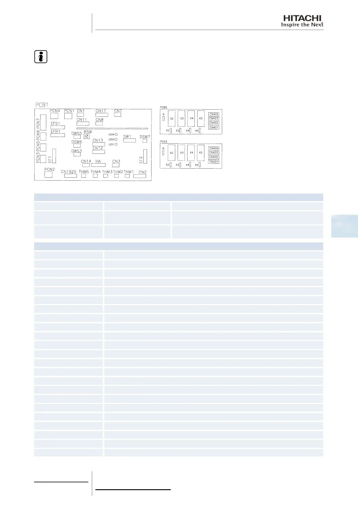
LED indicator
LED1 Green PCB power supply
LED3 Yellow
This LED indicates the transmission status between the indoor unit and the
remote control.
LED4 Red
This LED indicates the transmission status between the indoor unit and the
outdoor unit.
Connector indication
PCN1 220 V transformer
PCN5 PCB1 relay
PCN7 Power supply (1-R, 2-S, 3-N, 4-E)
THM1 Air inlet
THM2 Air outlet
EF1 Fuse
EF2 Fuse
EFS1 Fuse
EFR1 Fuse
CN1 Transformer (pins 1-2: 17.3 V/pins 3-4: 20.8 V)
CN2 Outdoor unit H-LINK control circuit
CN3 Optional input functions (only 2)
CN4 Optional input functions
CN7 Optional output functions (only 2)
CN8 Optional output functions (no. 1, no. 2, only 1)
CN11 PCB3 connection
CN12 Remote control jumper connection for several units
CN13 SW remote control
CN17 PCB2 connection
CN401 Fan motor relay
CN402 Fan motor relay
CN403 Fan motor relay
CN404 Fan motor relay
5 Control system
173
SMGB0063 rev. 1 - 10/2010
5