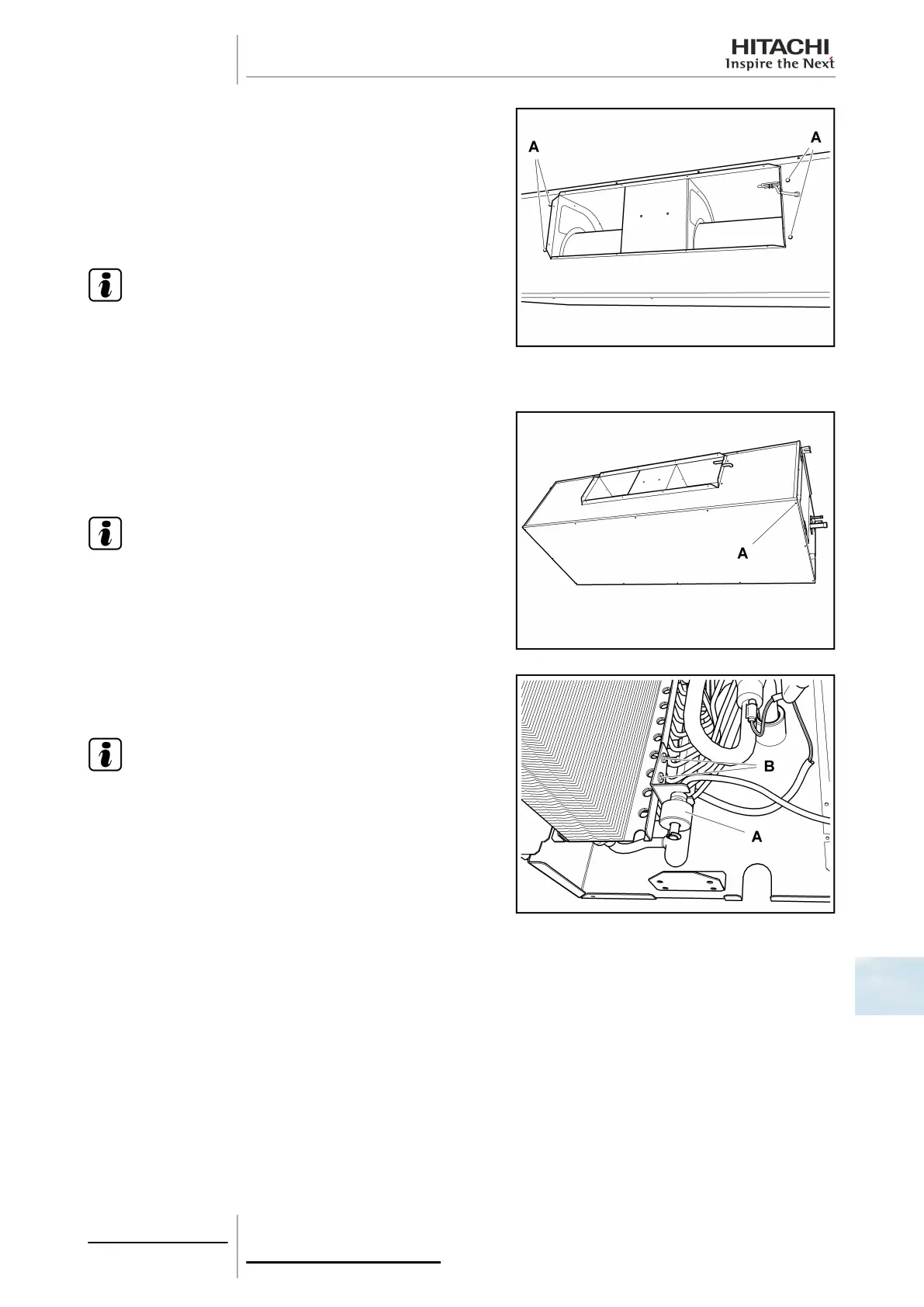
Remove the screws -A- on both sides of the fan and remove the
unit.
When fitting, connect the fan motor connector to the electrical box
in line with the previous configuration:
• Connector CN24 LSP (Low Static Pressure) ; (factory-
supplied).
• Connector CN25 HSP (High Static Pressure).
N O T E
The fan parts form an undividable unit. Their separate
dismantling and repair is not foreseen.
10.5.7 Removal of the float switch
Remove all screws -A- from the lower cover of the unit and separate
it.
Remove the drain pan Removal of the drain pan, see on page
305.
N O T E
To disconnect and remove the float switch, previously see the
chapter corresponding to the wiring diagrams in this Manual.
Loosen the resin nut securing the float switch -A- and remove it. If
the switch support is to be removed, remove screws -B-.
N O T E
The torque value of the resin nut is 0.3 - 0.4 Nm. If the torque
value is higher, the nut will be damaged.
10 Servicing
307
SMGB0063 rev. 1 - 10/2010
10