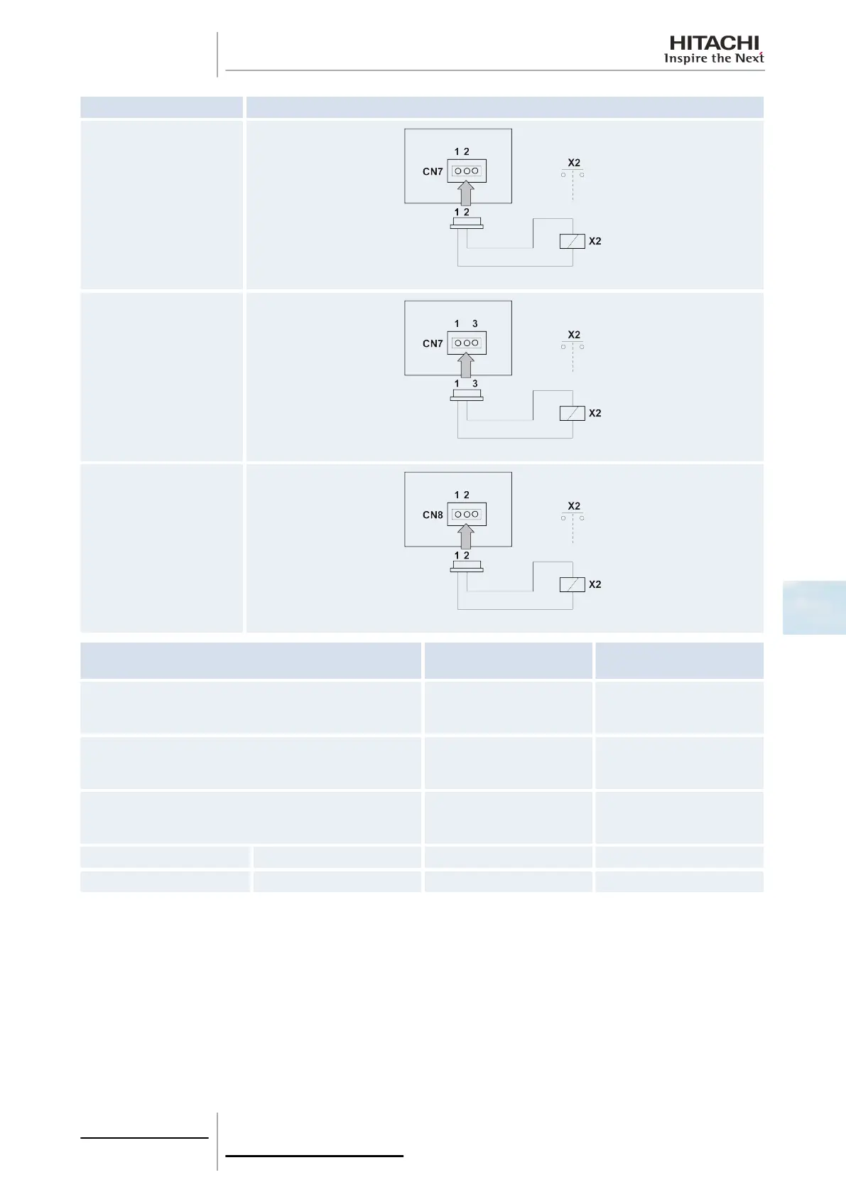
Indication Connections
o1
o2
o3
Component
Manufacturer or
specifications
Remarks
Auxiliary relay (X2)
Reduced power relay model
OMRON: MY1F or
equivalent
Voltage between the relay
terminals 12 Vdc, 75 mA
Contact (SS1) (x1) (example) Manual type
Voltage between the
contactor terminals 230 V,
5 mA
3-pin connector cable
Optional part PCC-1A
(capable of connecting the
connector (JST XHP-3)
Five cables with connectors
in one group
Cable (control) Voltage: 12 Vdc 0.5 mm
2
Cable (power) Voltage: 230 V 2.0 mm
2
Recommendations for wiring installation
• Keep the CN3 connector cables as short as possible.
• Try not to pull on the cable along the power line. The cables should be laid separately at a distance of over 30 cm. Cable
crossing is feasible.
• Where the cable along the power line is pulled, insert the cables through a metal pipe, earth one end of the pipe and
install a safety device such as an earth leakage breaker or smoke detector.
6.1.2 Optional signal configuration
The following tables describe the optional signals available on indoor units. Optional signals are configured using the remote
control, except for RPK-(1.0-4.0)FSN2M units in which they are configured using the DIP switches.
6 Optional functions
183
SMGB0063 rev. 1 - 10/2010
6