Hitachi hard disk drive specifications
223
11.43.3 Device Attribute Thresholds Data Structure
The following defines the 512 bytes that make up the Attribute Threshold information. This data structure is
accessed by the host in its entirety using the SMART Read Attribute Thresholds. All multi-byte fields shown in
these data structures follow the ATA/ATAPI-7 specification for byte ordering, namely that the least significant
byte occupies the lowest numbered byte address location in the field.
The sequence of active Attribute Thresholds will appear in the same order as their corresponding Attribute
Values.
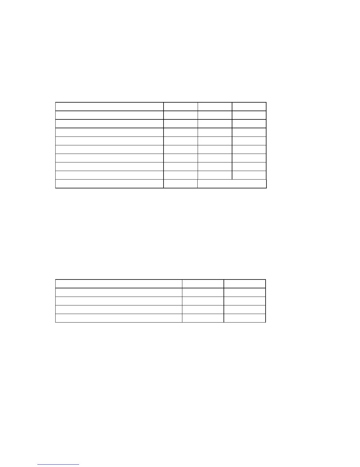
Data Structure Revision Number
Table 153 Device Attribute Thresholds Data Structure
11.43.3.1 Data Structure Revision Number
This value is the same as the value used in the Device Attributes Values Data Structure.
11.43.3.2 Individual Thresholds Data Structure
The following defines the 12 bytes that make up the information for each Threshold entry in the Device Attribute
Thresholds Data Structure. Attribute entries in the Individual Threshold Data Structure are in the same order and
correspond to the entries in the Individual Attribute Data Structure.
Attribute ID Number (01h to FFh)
Table 154 Individual Threshold Data Structure
11.43.3.3 Attribute ID Numbers
Attribute ID Numbers supported by the device are the same as Attribute Values Data Structures.
11.43.3.4 Attribute Threshold
These values are preset at the factory and are not meant to be changeable.
11.43.3.5 Data Structure Checksum
The Data Structure Checksum is the 2‟s compliment of the result of a simple 8-bit addition of the first 511 bytes
in the data structure.
 Loading...