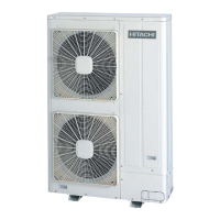
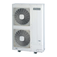
Combination of base units
Model
RAS-38
FSXN
RAS-40
FSXN
RAS-42
FSXN
RAS-44
FSXN
RAS-46
FSXN
RAS-48
FSXN
RAS-50
FSXN
RAS-52
FSXN
RAS-54
FSXN
Unit A
RAS-14
FSXN
RAS-16
FSXN
RAS-18
FSXN
RAS-18
FSXN
RAS-18
FSXN
RAS-18
FSXN
RAS-18
FSXN
RAS-18
FSXN
RAS-18
FSXN
Unit B
RAS-12
FSXN
RAS-12
FSXN
RAS-12
FSXN
RAS-14
FSXN
RAS-16
FSXN
RAS-18
FSXN
RAS-18
FSXN
RAS-18
FSXN
RAS-18
FSXN
Unit C
RAS-12
FSXN
RAS-12
FSXN
RAS-12
FSXN
RAS-12
FSXN
RAS-12
FSXN
RAS-12
FSXN
RAS-14
FSXN
RAS-16
FSXN
RAS-18
FSXN
Connection kit MC-30AN
a
Gas ø38.1 ø38.1 ø38.1 ø38.1 ø38.1 ø38.1 ø38.1 ø38.1 ø38.1
Liquid ø19.05 ø19.05 ø19.05 ø19.05 ø19.05 ø19.05 ø19.05 ø19.05 ø19.05
b
Gas ø28.6 ø28.6 ø28.6 ø31.75 ø31.75 ø31.75 ø31.75 ø31.75 ø31.75
Liquid ø15.88 ø15.88 ø15.88 ø19.05 ø19.05 ø19.05 ø19.05 ø19.05 ø19.05
c
Gas ø25.4 ø28.6 ø28.6 ø28.6 ø28.6 ø28.6 ø28.6 ø28.6 ø28.6
Liquid ø12.7 ø12.7 ø15.88 ø15.88 ø15.88 ø15.88 ø15.88 ø15.88 ø15.88
d
Gas ø25.4 ø25.4 ø25.4 ø25.4 ø28.6 ø28.6 ø28.6 ø28.6 ø28.6
Liquid ø12.7 ø12.7 ø12.7 ø12.7 ø12.7 ø15.88 ø15.88 ø15.88 ø15.88
e
Gas ø25.4 ø25.4 ø25.4 ø25.4 ø25.4 ø25.4 ø25.4 ø28.6 ø28.6
Liquid ø12.7 ø12.7 ø12.7 ø12.7 ø12.7 ø12.7 ø12.7 ø12.7 ø15.88
If the main refrigerant pipe specified in the table is not available at the installation location, select the size given in brackets.
In this case, prepare a suitable reducer.
Main pipe Alternative pipe and reducer Main pipe Alternative pipe and reducer
ø9.53 (ø9.53-ø12.7) ø25.4 (ø25.4-ø28.6)
ø12.7 (ø12.7-ø15.88) ø28.6 (ø28.6-ø31.75)
ø15.88 (ø15.88-ø19.05) ø31.75 (ø31.75-ø34.9)
ø19.05 (ø19.05-ø22.2) ø38.1 (ø38.1-ø41.3)
ø22.2 (ø22.2-ø25.4) – –
¿ Gas stop valve
Make
sure that valves -A- and -J- (not used) are completely closed.
Connect the charge pipe to the stop valve -B- and release gas from
the gas pipe -C-.
Remove the cover -F- from the stop valve.
Cut off the end -D- of the stop pipe -E- (ø6.35) and check that there
is no gas in the pipe -C-. Do not cut the end -H- of the stop pipe
(ø6.35) -I- to prevent leaks of refrigerant. If the end of the stop pipe
is cut, close it completely.
D A N G E R
Check that
there is no gas inside the pipe before removing the
stop pipe. Otherwise, the pipe may explode when heated with
the blow torch.
Remove the stop pipe at the welded section -G- using a blow torch
-K-. Special care should be taken to ensure that the flame from the
blow torch does not fall on the body of the stop valve -A-, on the
compressor -N- and cover or on the insulation bushings by inserting
a metal plate -L- in front of the oil return pipe -M-.
3 Piping work and
refrigerant charge
43
SMGB0065 rev. 1 - 12/2010
3

 Loading...


