11 C031 NO NC
12 C032 NO NC
13 C033 NO NC
14 C034 NO NC
15 C035 NO NC
Chart 8
SJ300 intelligent output terminal default setting
3.4 Expansion cards
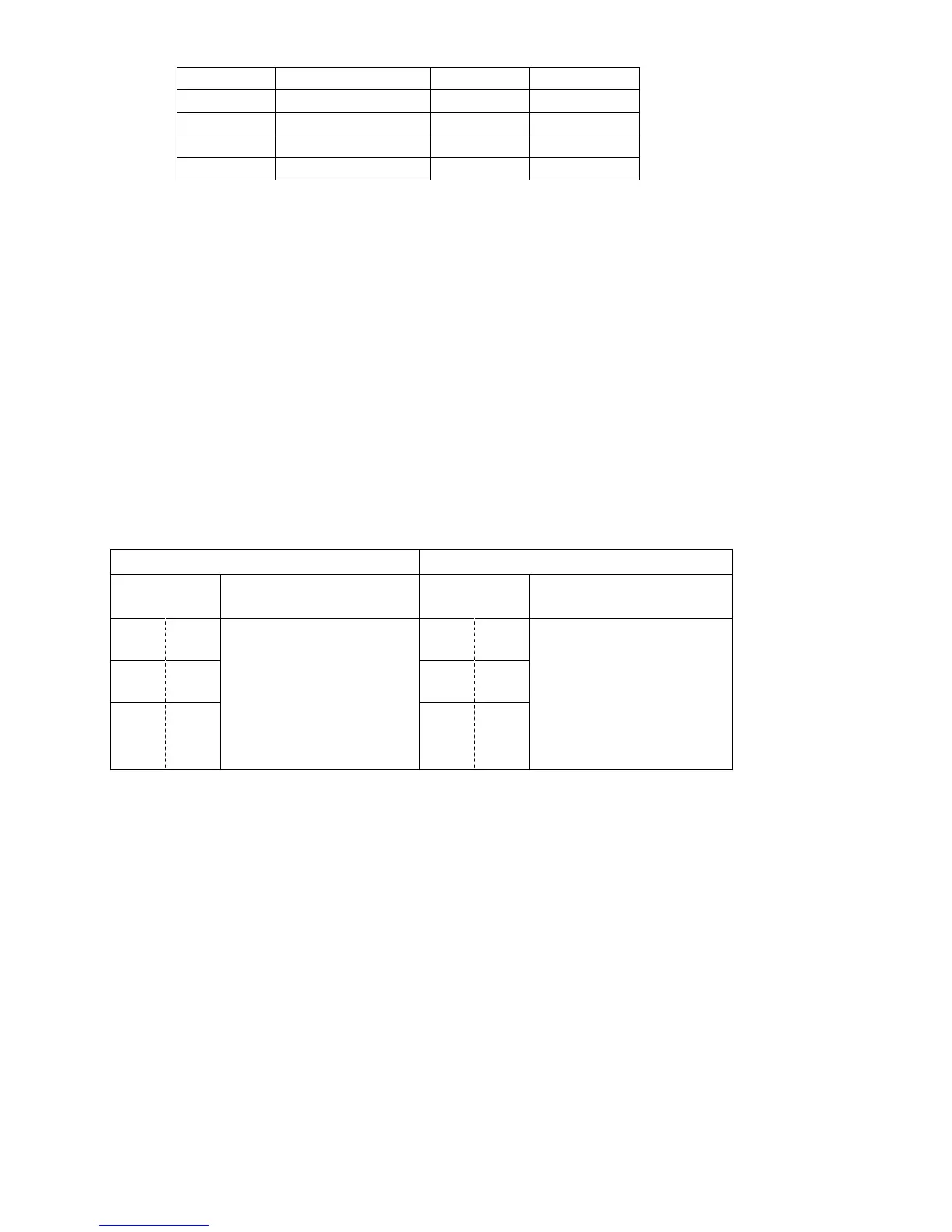
(1) J-RY (Relay output PCB)
Please use L300PTM (standard control signal) terminal block.
Refer to Chart 9 for its specifications.
J-RY(J300) L300PTM(SJ300)
Terminal
symbol
Terminal specifications
Terminal
symbol
Terminal specifications
RYA1 RYA0 11A 11C
RYB1 RYB0 12A 12C
RYC1 RYC0
AC250V, 2.5A (R load),
0.2A (I load)
DC30V, 3A (R load),
0.7A (I load)
Minimum load
AC100V, 10mA,
DC5V, 100mA
- -
AC250V, 5A (R load),
1A (I load)
DC30V, 5A (R load),
1A (I load)
Minimum load
AC100V, 10mA,
DC5V, 100mA
Chart 9
Relay output function comparison chart
(2) J-R0T0 (Control power supply PCB)
The SJ300 has R0T0 terminals as standard.
When supplying the R0T0 terminals with power externally, remove J51 jumper beforehand.
(3) J-FB (Feedback PCB)
Please use SJ-FB.
The SJ-FB does not have the analog monitor (MA1 and MA2) which the J-FB has.
When this function is required, please use the analog monitor provided on the SJ300 (AM and
AMI).
14/24

 Loading...


