H
D
W
Chapter 3 - Wiring
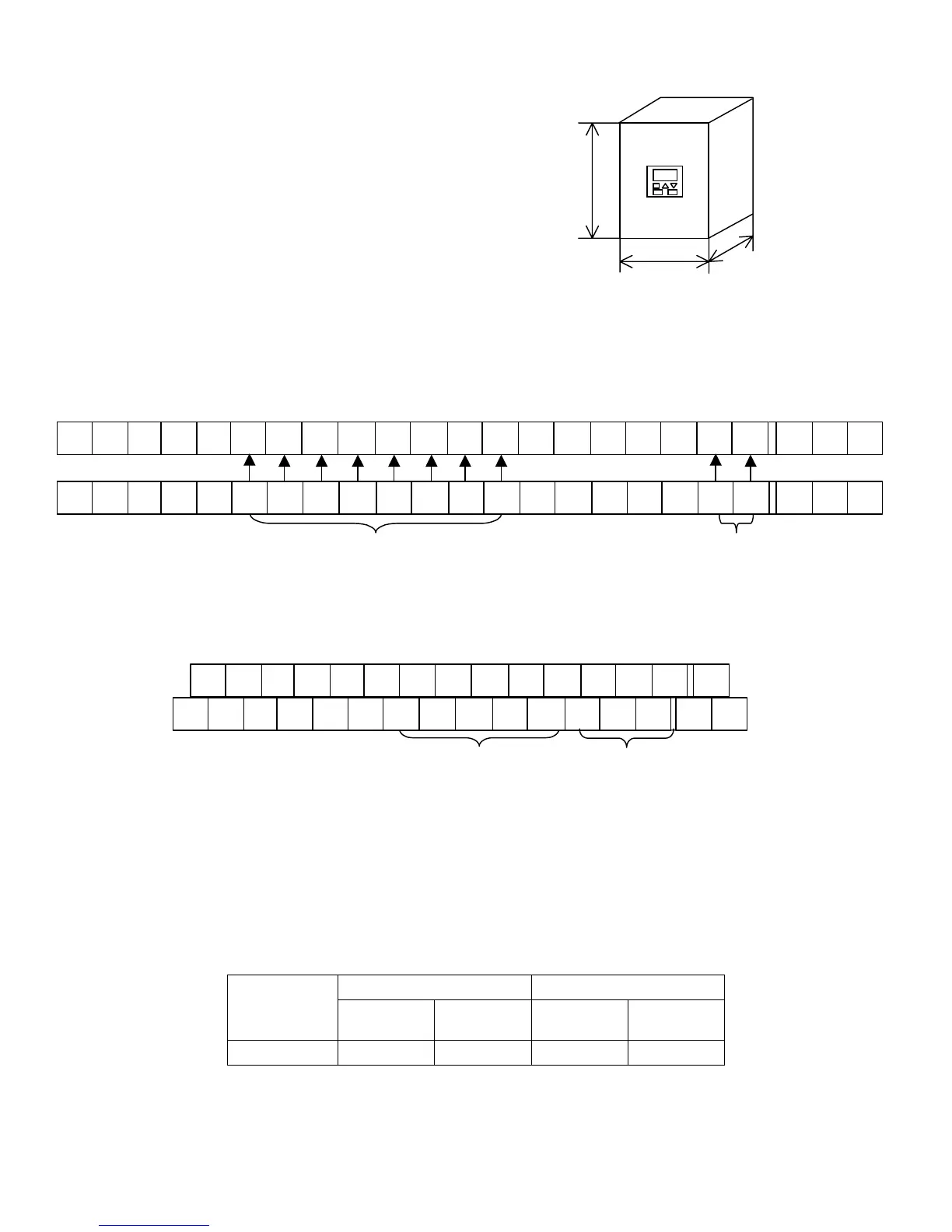
The arrangement of the SJ300’s control circuit terminals is shown below. (Figure 12 and 13)
Please note that J300’s control circuit terminals are arranged vertically while SJ300’s are
arranged horizontally.
Intelligent
output
terminals
Intelligent input terminals
FRS
CF2
CH1
T
OI
FW
CF1
L2
L1
JG
L
RS
H
REVPLC
P24FM
CM1
L0
CM2
RUN
FA1
4
6
5
2
OI
FW
7
L2
L13 L
1
H
8PLC
P24FM
CM1
L0
CM2 12 11
Figure 12
J300’s control circuit terminals
Intelligent input terminals
3
CM1
5
14
TH 8 1
13
11
FW
M FMH O2
47
6
15P24
CM1
2
CM2
12
PLCOI
MIL O
L1
L2
L0
Intelligent
output
terminals
Figure 13
SJ300’s control circuit terminals
J300 SJ300
Motor
capacity (kW)
Screw
diameter
Terminal
width (mm)
Screw
diameter
Terminal
width (mm)
1.5 to 132 M3 6.2 M3 6.4
10/24

 Loading...


