EasyManuals Logo

Hitachi Virtual Storage Platform User Manual

Hitachi Virtual Storage Platform
146 pages
To Next Page IconTo Next Page
To Previous Page IconTo Previous Page
Page #92 background imageLoading...
Page #92 background image
Hitachi VSP User and Reference Guide
3–6
System Components
All components are configured in redundant pairs to prevent system failure.
All the components can be added, removed, or replaced while the storage
system is in operation.
The Virtual Storage Platform can be configured with two types of drive
chassis:
An LFF DKU (disk unit) chassis, which contains up to 80 LFF (3-1/2 inch)
HDD or SSD drives
An SFF DKU (disk unit) chassis, which contains up to 128 SFF (2-1/2
inch) HDD or SSD drives
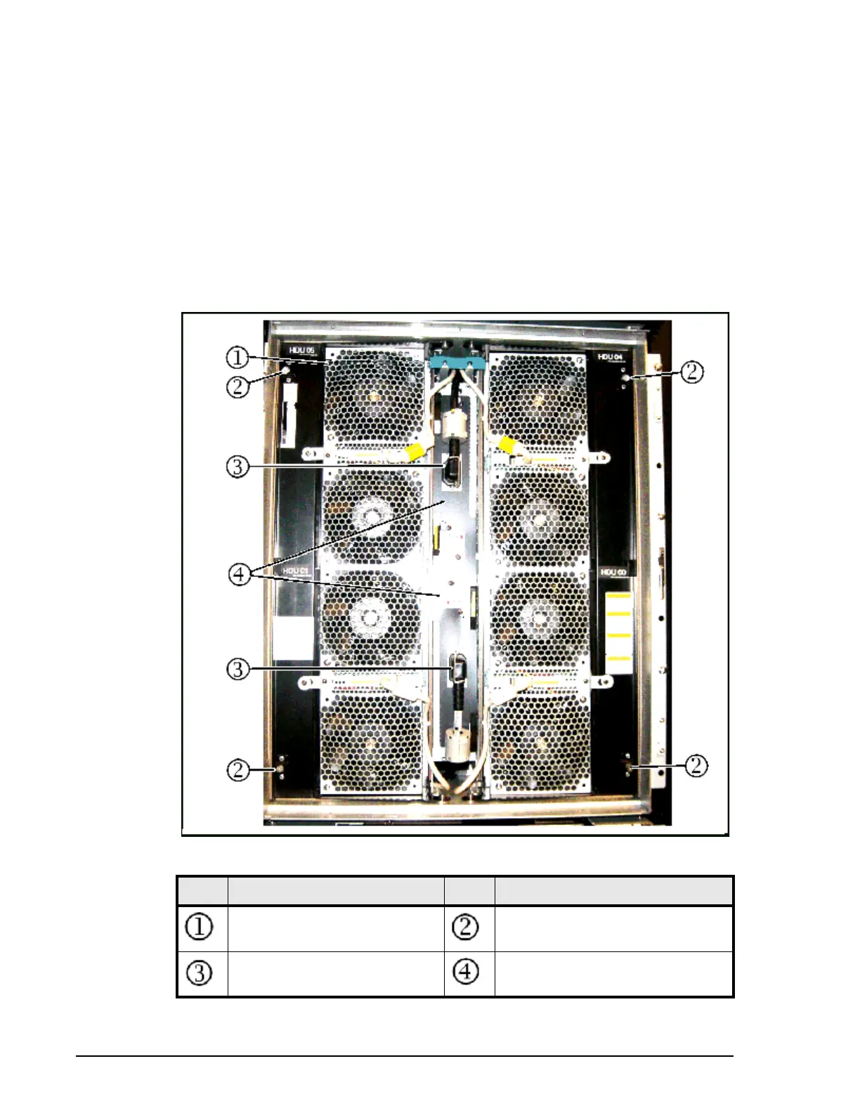
The following illustration shows the rear view of a DKU drive chassis. The
front view is exactly like the rear view. The table following the illustration
describes the drive chassis components.
Figure 3-4 Drive Chassis
Item Description Item Description
Fan (8 total) Fan assembly lock screw
(Loosen screw to open fan door.)
Power Cable HDD Power Supply

Table of Contents

Questions and Answers:

Question and Answer IconNeed help?

Do you have a question about the Hitachi Virtual Storage Platform and is the answer not in the manual?

Hitachi Virtual Storage Platform Specifications

General IconGeneral
Drive TypesSSD, SAS
RAID SupportRAID 1, RAID 5, RAID 6, RAID 10
ConnectivityFibre Channel, iSCSI, FCoE
Form FactorRack-mounted
CategoryEnterprise Storage System
Data ReductionDeduplication and Compression (capabilities vary by model and software version)
Operating System CompatibilityWindows, Linux, UNIX, VMware
High AvailabilityRedundant components
ScalabilityScale-up and scale-out
ModelVirtual Storage Platform (VSP)

Related product manuals