Hitachi VSP User and Reference Guide
3–2
System Components
Controller chassis
The controller chassis provides system logic, control, memory, and
monitoring, as well as the interfaces and connections to the disk drives and
the host servers. The controller chassis consists of the following
components:
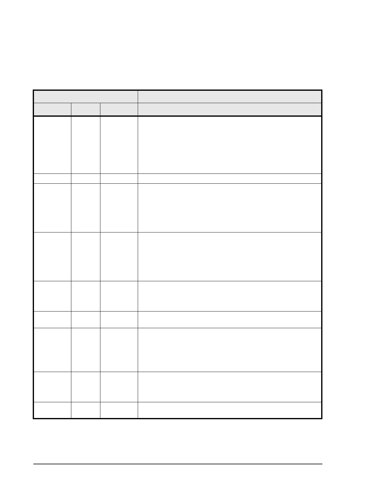
Table 3-1 Controller chassis
Item Description
Name Min Max .
Service
Processor
(SVP)
1 2 A custom PC that implements system configuration settings and
monitors the system operational status. Connecting the SVP to
service center enables the storage system to be remotely
monitored and maintained by the Hitachi Data Systems support
team. This significantly increases the level of support that Hitachi
Data Systems can provide to its customers Note: In a system
with two SVPs, both are installed in the controller chassis in
system 0.
Hub 1 2 Connects the switches, adapters, and Service Processors.
front-end
director
(FED)
28 if 4 BEDs
installed.
-------------
12 if no
BEDs
installed.
A FED is an interface board that provides connection to the host
servers. It provides the channel interface control functions and
intercache data transfer functions between the storage system
and the host servers. It converts the data format between CKD
and FBA. The FED contains an internal processor and 128 bytes
of edit buffer memory.
back-end
director
(BED)
0 if
diskless
---------
-
2 with
drives
4 A BED is an interface board that provides connection to the disk
drives and SSDs. Provides the control functions for data transfer
between drives and cache. The BED contains DRR (Data Recover
and Reconstruct), a parity generator circuit. It supports eight
FIBRE path and offers 32 KB of buffer for each FIBRE path.
Switches 2 4 The full duplex switches serve as the data interconnection
between the FEDs, BEDs, and cache memory. They also connect
the control signals between the virtual storage directors
(microprocessors) and the cache memory.
Microproces
sor
2 4 Quad core, 2.33 GHz MPs are independent of the CHAs and DKAs
and can be shared across FEDs and FED
Cache
memory
adapter
(CPC)
2 4 The cache is an intermediate buffer between the channels and
drives. Each cache memory module has a maximum capacity of
128 GB (64 GB × 2 areas). It is available and controlled as two
areas of cache (cache A and cache B). If the power fails, the
cache is protected from data loss by backup batteries and the
cache flash memory.
AC-DC
power
supply
2 4 200-220 VAC input. Provides power to the controller chassis in a
redundant configuration to prevent system failure. Up to four
power supplies can be used as needed to provide power to
additional components.
Cooling fan 10 10 Each fan unit contains two fans to ensure adequate cooling in
case one of the fans fails.