System Components
3–5
Hitachi VSP User and Reference Guide
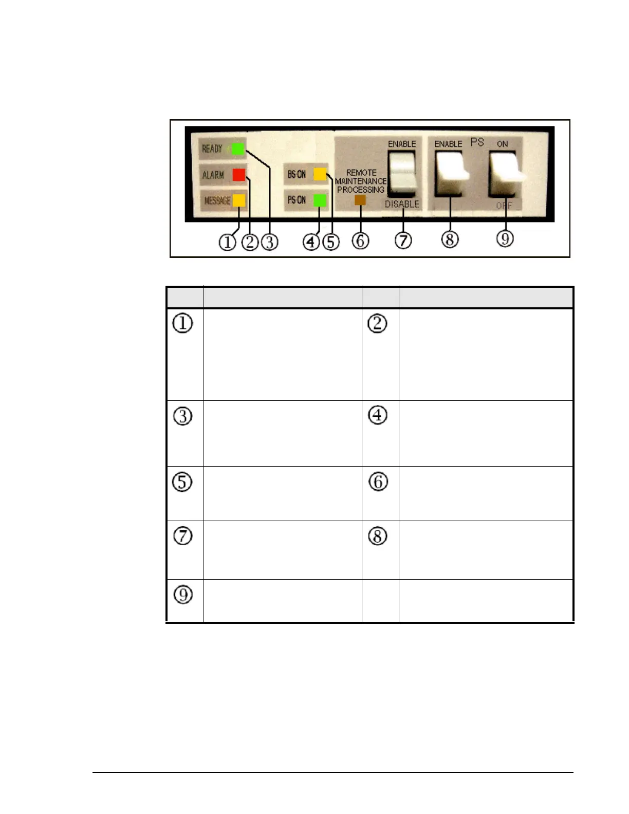
System control panel
The following illustration shows the Virtual Storage Platform system control
panel. The table following the illustration explains the purpose of each of the
controls and LEDs on the panel.
Drive chassis
The drive chassis (factory designation DKU) includes two back-to-back-disk
drive assemblies. Each assembly includes disk drives and/or flash drives,
SSW boards, HDD PWR boards, eight cooling fans, and two power supplies.
Figure 3-3 Virtual Storage Platform System Control Panel
Item Description Item Description
MESSAGE - Amber LED
ON: indicates that a SIM
(Message) was generated from
either of the clusters. Applied to
both storage clusters.
Blinking: Indicates that a SVP
failure has occurred.
ALARM - Red LED
Indicates DC under voltage of any
DKC part, DC over current,
abnormally high temperature, or
that an unrecoverable failure
occurred.
READY - Green LED Indicates
that input/output operation on
the channel interface is enabled.
PS ON - Green LED
Indicates that the system is
powered on, that the POST is
complete, and that the system has
booted up and is ready for use.
BS ON - Amber LED
Indicates that the “basic supply”
the sub-Power supplying cluster
1 or cluster 1 is on.
REMOTE MAINTENANCE
PROCESSING - Amber LED
Indicates that the system is being
remotely maintained.
REMOTE MAINTENANCE
ENABLE/DISABLE - switch
When ON, permits remote
maintenance.
PS SW ENABLE - switch
Used to enable the PS ON/PS OFF
switch.
PS ON/PS OFF - switch
Turns the system power on or
off.
--