Table of Contents
WIRELESS IQ EQUIPMENT .....................................................................................................1
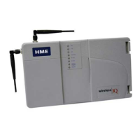
Wireless IQ Base Station ..........................................................................................................................2
External Features ..................................................................................................................................2
COMMUNICATOR
®
................................................................................................................................4
Features and Controls ...........................................................................................................................4
How to Wear the COMMUNICATOR
®
...............................................................................................4
How to Use the COMMUNICATOR
®
Controls...................................................................................5
COMMUNICATOR
®
Registration.......................................................................................................5
Battery Removal and Replacement.......................................................................................................7
Battery Charger.........................................................................................................................................8
WIRELESS IQ OPERATION......................................................................................................9
Changing Languages.................................................................................................................................9
Obtaining Communicator Status...............................................................................................................9
Single-Lane Operation (one base station for one speaker post).............................................................10
Dual-Lane Operation (two base stations for two speaker posts)............................................................11
Tandem Operation (two base stations for two speaker posts)................................................................12
Internal Communication .........................................................................................................................13
Speed-Team Operation ...........................................................................................................................14
Wired Backup System.............................................................................................................................14
Message Repeater Operation...................................................................................................................15
EQUIPMENT CARE AND CLEANING ..................................................................................16
Handling the Equipment Properly...........................................................................................................16
Cleaning the Equipment..........................................................................................................................16
IN CASE OF PROBLEMS .........................................................................................................17
Base Station Internal Controls and Indicators.........................................................................................20
EQUIPMENT SPECIFICATIONS............................................................................................21
FCC NOTICE...............................................................................................................................22
Figures and Diagrams
Figure 1. Wireless IQ standard equipment.................................................................................................1
Figure 2. Base station with front door open ...............................................................................................2
Figure 3. COMMUNICATOR
®
controls....................................................................................................4
Figure 4. Correct wearing of the headset....................................................................................................4
Figure 5. Registration buttons and indicators.............................................................................................6
Figure 6. Belt-pac battery-release latch......................................................................................................7
Figure 7. Headset battery-release latch ......................................................................................................7
Figure 8. Batteries in charger .....................................................................................................................8
Figure 9. Typical Tandem drive-thru .......................................................................................................12
Figure 10. S2 switch on Switcher Board....................................................................................................14
Figure 11. Base station internal features ....................................................................................................20
© 2009 HM Electronics, Inc.
The HME logo and product names are registered trademarks of HM Electronics, Inc. All rights reserved.
Illustrations in this publication are approximate representations of
the actual equipment, and may not be exactly as the equipment appears.