Communicator Configuration 70 (124)
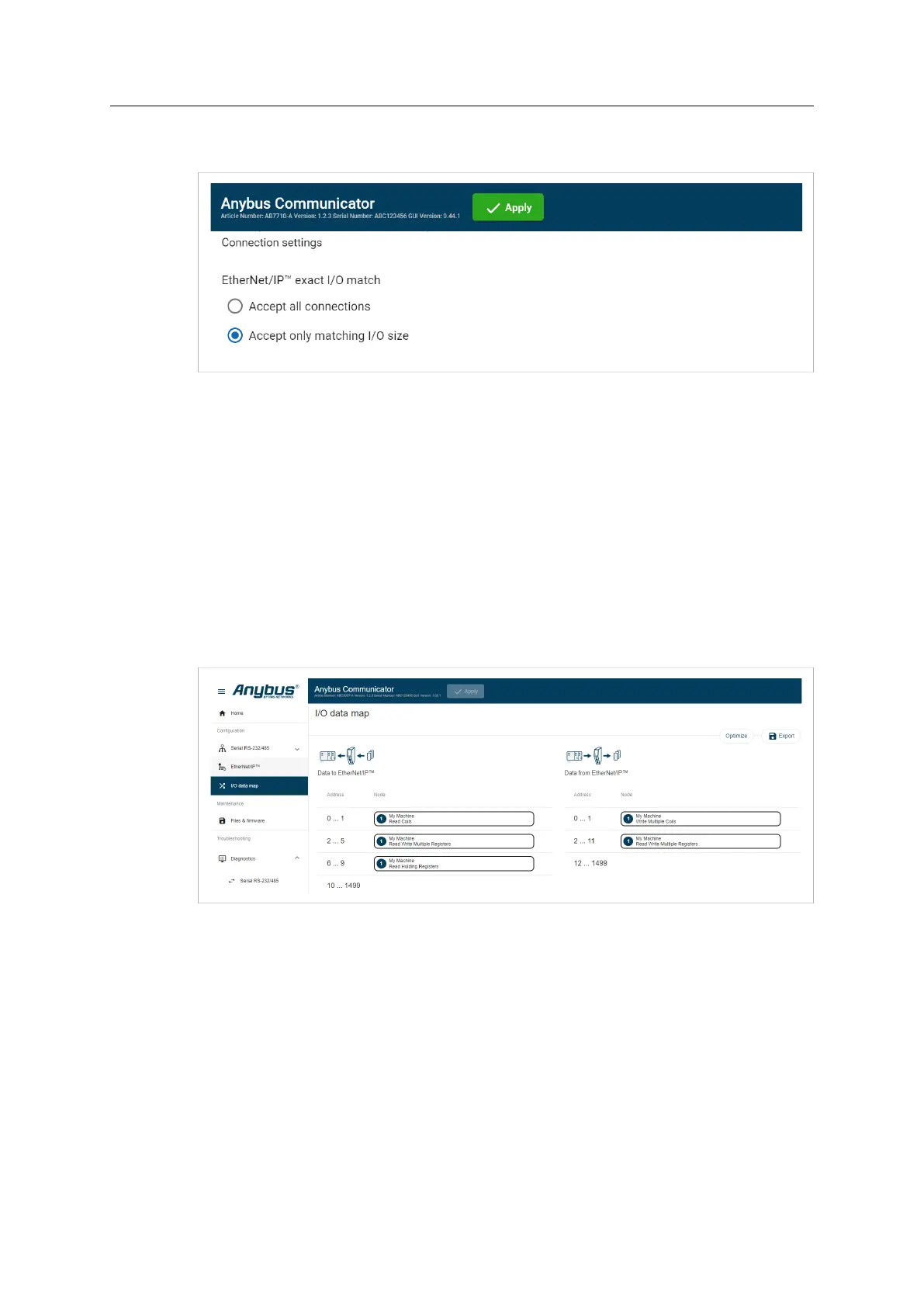
7.9.6 Connection Settings
When the EtherNet/IP Client (PLC) opens a connection to the Communicator, it specifies an I/O
data size.
By default the Communicator is set to Accept Only Matching I/O Sizes.
The connections must match the I/O size configured on the EtherNet/IP page, refer to To Use
Automatic I/O Sizes, p. 67 and To Configure I/O Sizes Manually, p. 67.
You can change to Accept All Connections.
The Communicator will accept all connections with an I/O size that is equal to or smaller than
the configured I/O size in the Communicator.
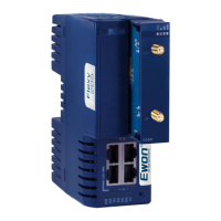
7.10 I/O Data Map
On the I/O data map page the data communication between the subnetwork (Node) and the
high level network (PLC) is mapped.
The allocated I/O area is auto-generated based on how the settings on the Serial communication
page and the Nodes and transactions page are configured.
It is possible to set the I/O area manually, if you want to pro-actively allocate more I/O for future
expansions without re-configuring the PLC. Refer to To Configure I/O Sizes Manually, p. 67.
There are three areas: Data from EtherNet/IP, Data to EtherNet/IP and General Areas. Refer to
Map Area, p. 73.
Anybus
®
Communicator
™
User Manual
SCM-1202-152 1.10 en-US