TM-260 273 Page 15Handler 190
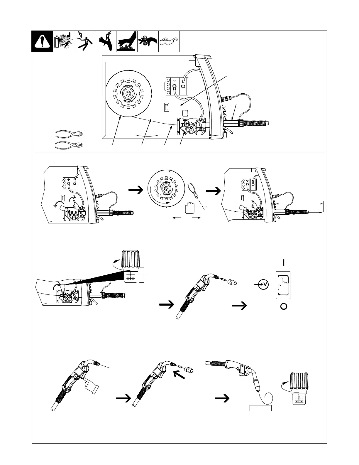
3-13. Threading Welding Wire
1 Wire Spool
2 Welding Wire
3 Inlet Wire Guide
4 Pressure Adjustment Knob
5 Drive Roll
6 Gun Conduit Cable
Lay gun cable out straight.
Tools Needed:
Pull and hold wire; cut off end.
Remove gun nozzle
and contact tip.
Open pressure assembly. Make sure
feed roll is set to correct groove to
match wire size (see Section 7-4).
Push wire thru guides into gun;
continue to hold wire.
. Hold wire tightly to keep it
from unraveling.
260 587-A
WOOD
Feed wire to check drive roll pressure.
Tighten knob enough to prevent slipping.
Cut off wire. Close door.
Press gun trigger until wire comes
out of gun.
Turn power on. Be sure that Voltage range
switch is set to range 1, 2, 3, 4, 5, 6, or 7 to
feed wire. Rotate knob until it “clicks” into
detent. Wire will not feed if range switch is
set between ranges.
6 in
(150 mm)
Tighten
. Use pressure indicator
scale to set a desired
drive roll pressure.
Pressure
Indicator
Scale
Tighten
Be sure that wire is positioned
in proper feed roll groove.
Close and tighten pressure
assembly, and let go of wire.
Be sure that tip matches wire diameter.
Reinstall contact tip and nozzle.
4 in
(120 mm)
6
13
4
52