EasyManuals Logo

Hobart Handler 190 Technical Manual

Hobart Handler 190
48 pages
To Next Page IconTo Next Page
To Previous Page IconTo Previous Page
Page #28 background imageLoading...
Page #28 background image
TM-260 273 Page 26 Handler 190
SECTION 7 − MAINTENANCE
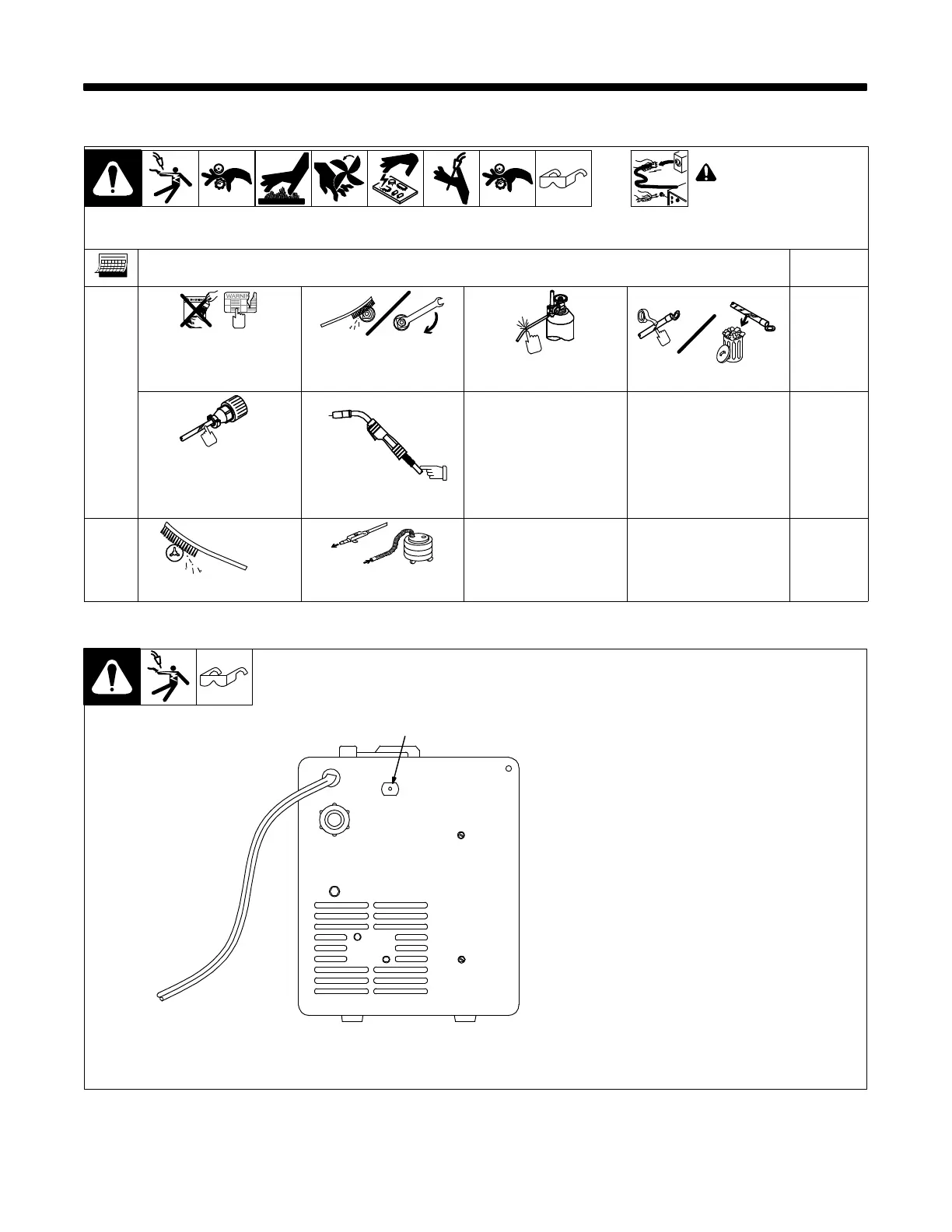
7-1. Routine Maintenance
! Disconnect power
before maintaining.
. Maintain more often
during severe conditions.
n = Check Z = Change ~ = Clean l = Replace
* To be done by Factory Authorized Service Agent
Reference
Every
3
Months
l Unreadable Labels ~ Weld Terminals l Damaged Gas Hose nl Weld Cables
nl Cords nl Gun Cables
Every
6
Months
OR
~ Drive Rolls ~ Inside Unit
7-2. Overload Protection
802 441
1 Supplementary Protector CB1
CB1 protects unit from overload. If
CB1 opens, unit shuts down.
Reset supplementary protector.
1
7-3. Drive Motor Protection
Drive motor protection circuit protects drive motor from overload. If drive motor becomes inoperative, release gun
trigger and wait until protection circuit resets allowing drive motor to feed wire again.

Other manuals for Hobart Handler 190

Questions and Answers:

Question and Answer IconNeed help?

Do you have a question about the Hobart Handler 190 and is the answer not in the manual?

Hobart Handler 190 Specifications

General IconGeneral
Input Voltage230 V
Amperage Output25-190 A
Weldable MaterialsSteel, Stainless Steel, Aluminum
Weight68 lbs
Spool Size Capacity4 or 8 inch
Input Current20 A
Input Frequency60 Hz
ProcessesMIG (GMAW), Flux-Cored (FCAW)
Input PhaseSingle Phase
Duty Cycle30% at 130 A
Material Thickness24 ga. - 5/16 in. (Steel)
Wire Size Range0.023-0.035 in (0.6-0.9 mm) solid, 0.030-0.045 in (0.8-1.2 mm) flux-cored

Related product manuals