TM-260 273 Page 4 Handler 190
2-4. Volt-Ampere Curves
The volt-ampere curves show the
minimum and maximum voltage
and amperage output capabilities of
the welding power source. Curves
of other settings fall between the
curves shown.
ssb1.1 10/91 − 248 833-A
0
5
10
15
20
25
30
0 10 20 30 40 50 60 70 80 90 100 110 120 130 140 150 160 170 180 190 200
Voltage
Amperage
1
2
3
4
5
6
7
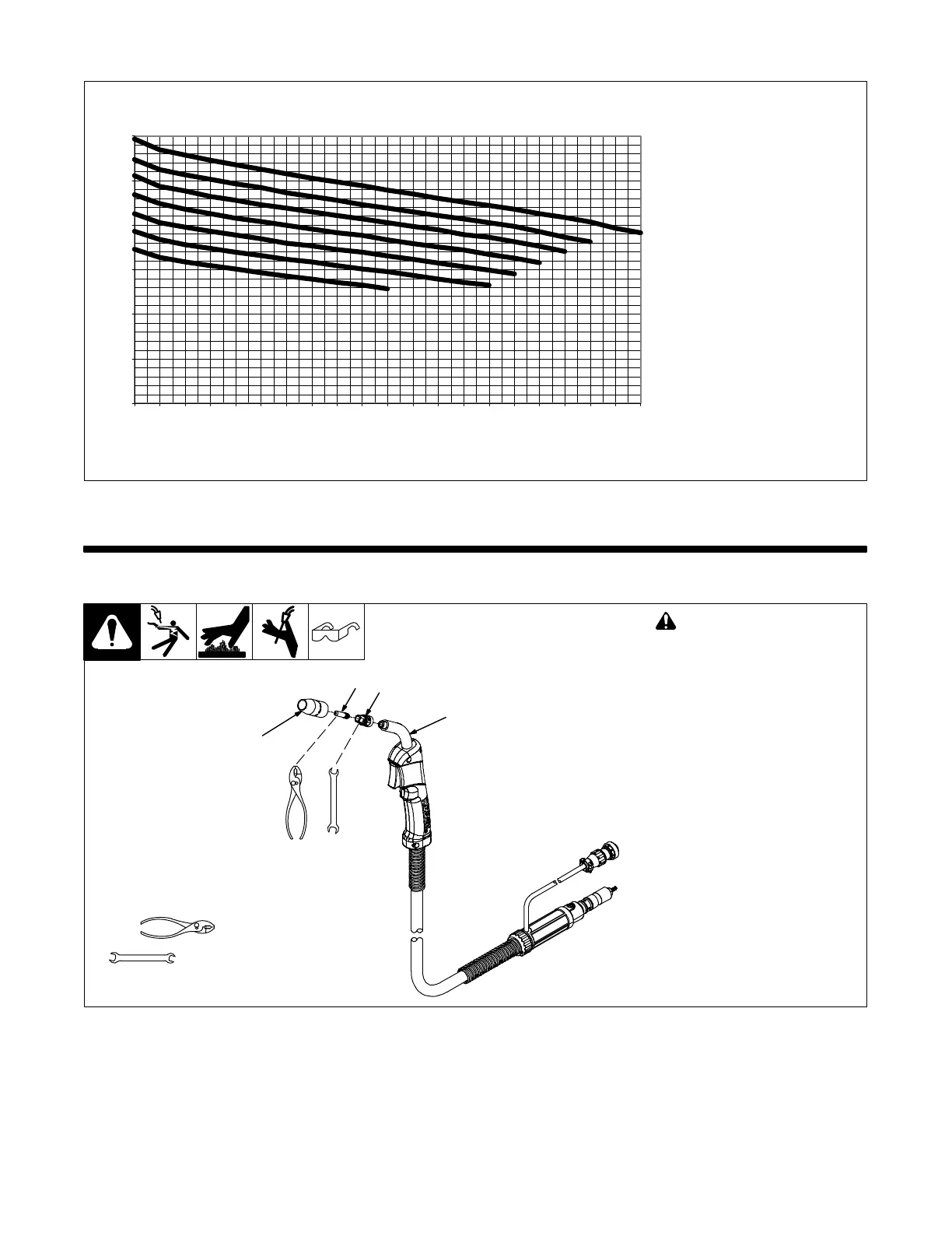
SECTION 3 − INSTALLATION
3-1. Installing Nozzle, Contact Tip, And Adapter
Ref. 243 839-A
! Turn off welding power
source.
1 Nozzle
2 Contact Tip
3 Tip Adapter
. Wire size stamped on tip − check
and match wire size.
Tools Needed:
8 mm
Head
Tube
8 mm
1
3
2