10 TF 50 E | Version 1.05
Setting up and connecting
7 Setting up and connecting
7.1 Installation site requirements
The installation site should meet the following criteria:
- The support surface must be level, firm and free of
vibrations.
- The support surface must not be permeable to
lubricants.
- The installation room or workspace must be dry
and well ventilated.
- There must be sufficient space for operating
personnel to work and handle materials as well as
perform adjustment and maintenance tasks.
- There must be adequate lighting at the installation
site.
- An extraction system must also be installed at the
site!
7.2 Setting up the table router
Securing the machine
Prior to use, we recommend securing the machine to a
workbench via the four holes.
Step 1: The mounting surface must be pre-drilled in
accordance with the spacing of the two mounting
holes.
Step 2: The machine must be secured in position using
screws (not supplied). The screws must be a
sufficient length: Take into account the thickness
of the work surface on which the machine is
mounted.
Step 3: Use the washers and nuts on the underside of
the work surface to attach the bolts.
Step 4: The work surface must be large enough to
prevent the machine from tipping over while
working.
7.3 Installing the spindle fence
The spindle fence is dismantled on delivery. Before
starting work, the fence must be assembled and
mounted on the work table.
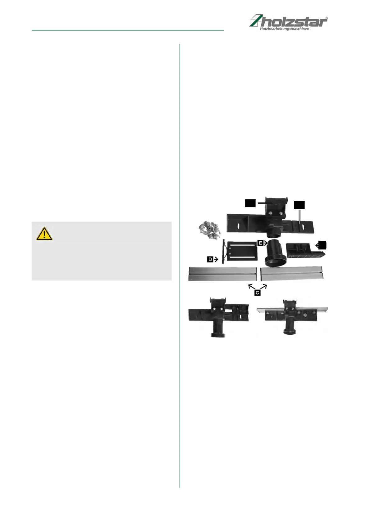
Spindle fence consisting of:
Main support (item A1, Fig. 5)
Attachment (item A2, Fig. 5)
Fence support (item B, Fig. 5)
Stop rails, 2 units (item C, Fig. 5)
Clamping bracket (item D, Fig. 5)
Suction nozzle (item E, Fig. 5)
Step 1: Assembly of parts A and B:
Push the fence support (item B, Fig. 5) into the
groove on the main support (item A1, fig. 5).
Then insert an M6x25 carriage bolt through the
hole and screw a plastic flanged nut with washer
onto it.
Fig. 5: Installing the spindle fence
Step 2: Install the stop rails (item C, Fig. 5). Insert two
fillister screws into the mounting openings, fit
with a washer a plastic cap nut, and tighten by
hand. Then slide the stop rail with the groove
onto the heads of the carriage bolts. Now tighten
both plastic flanged nuts.
Carry out the same operation on the other side of
the fence.
Make sure that the stop rails (item C, Fig. 5) are
fitted in the right direction.
Make sure that the stop rails (item C, Fig. 5) are
fitted at the same height as the main support and
attachment (A1 and A2).
Step 3: Fit the clamping bracket (item D, Fig. 6) to the
fence using 2 carriage bolts, 2 washers and 2
plastic flanged nuts.
CAUTION!
Risk of injury from an unstable machine!
Set up the machine on a stable surface and check that
it is stable.
Pull out the mains plug before carrying out any adjust-
ment or maintenance work!
A1
A2
B