Start up
TF 50 E | Version 1.05 13
7.10 Electrical connection
When connecting the cable to the power supply, make
sure that the cable properties (voltage, mains frequency,
fuse protection) match the information on the rating plate
and for the motor.
Step 1: Check that the table router is switched off.
Step 2: Connect the machine to the mains power supply
and check the rotational direction of the motor.
8 Start up
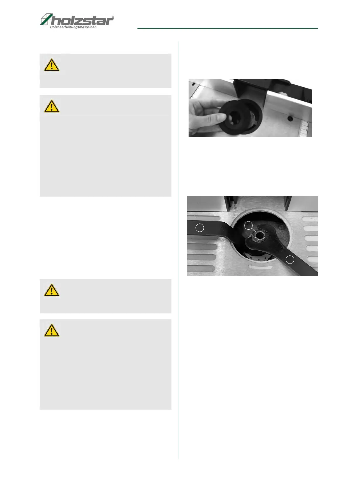
Installing and changing the tool holder (item 3, Fig. 16)
Step 1: Before changing the tool holder, pull out the
mains plug on your machine.
Step 2: Remove the table rings (Fig. 15).
Fig. 15: Installing and changing the tool holder
Step 3: Lock the spindle located below the tool holder
using a wrench (item 1, Fig. 16).
Step 4: Loosen the tool holder lock nut (item 3, Fig. 16) in
an anti-clockwise direction using a suitable
wrench (item 2, Fig. 16).
Fig. 16: Installing and changing the tool holder
Step 5: Select the correct tool holder that corresponds
exactly to the diameter of the cutter and then
insert.
Step 6: Tighten the nut on the tool holder in a clockwise
direction
while securing the spindle in position
with the second wrench. Before using the
machine, make sure that the milling element is
securely attached to the end of the spindle.
Step 7: Return the table rings to their original position.
Step 8: Use the scale on the table to adjust the fence
according to requirements.
Step 9: Connect the extraction system. We strongly
recommend connecting an extraction system to
keep the tool free of chips, cool the motor and
make workpieces easier to feed into the
machine.
Step 10: Reconnect the machine to the mains power
supply.
ATTENTION!
Work on the electrical installation must always be car-
ried out by a qualified electrician.
ATTENTION!
1. The machine may only be operated in combina-
tion with a residual-current device (RCD, max. resid-
ual current of 30mA).
2. If the table router is operated with an extension
cable, make sure that the cross-section of the cable
is correct.
Extension cables with a maximum length 25 m must
have a cross-section of 1.5 mm
2
, and extension cords
> 25 m in length must have a cross-section of 2.5 mm
2
.
3. Always unwind a cable reel completely.
Failure to do so can damage the cable reel or even
cause a fire.
ATTENTION!
Before starting up the machine, check the electrical
connection, cables and contacts.
ATTENTION!
The table router has one spindle that must be perpen-
dicular to the horizontal surface of the table. The spin-
dle is used to attach milling tools, discs and forming
cutters.
Only cutters with a maximum diameter of 80 mm can
be used on the table router. If larger diameters are re-
quired, we recommend working in
several steps and repeatedly adjusting the height us-
ing the adjustment knob, or gradually adjusting the
fence.
1
2
3