Setting up and connecting
TF 50 E | Version 1.05 11
Fig. 6: Fitting the clamping bracket
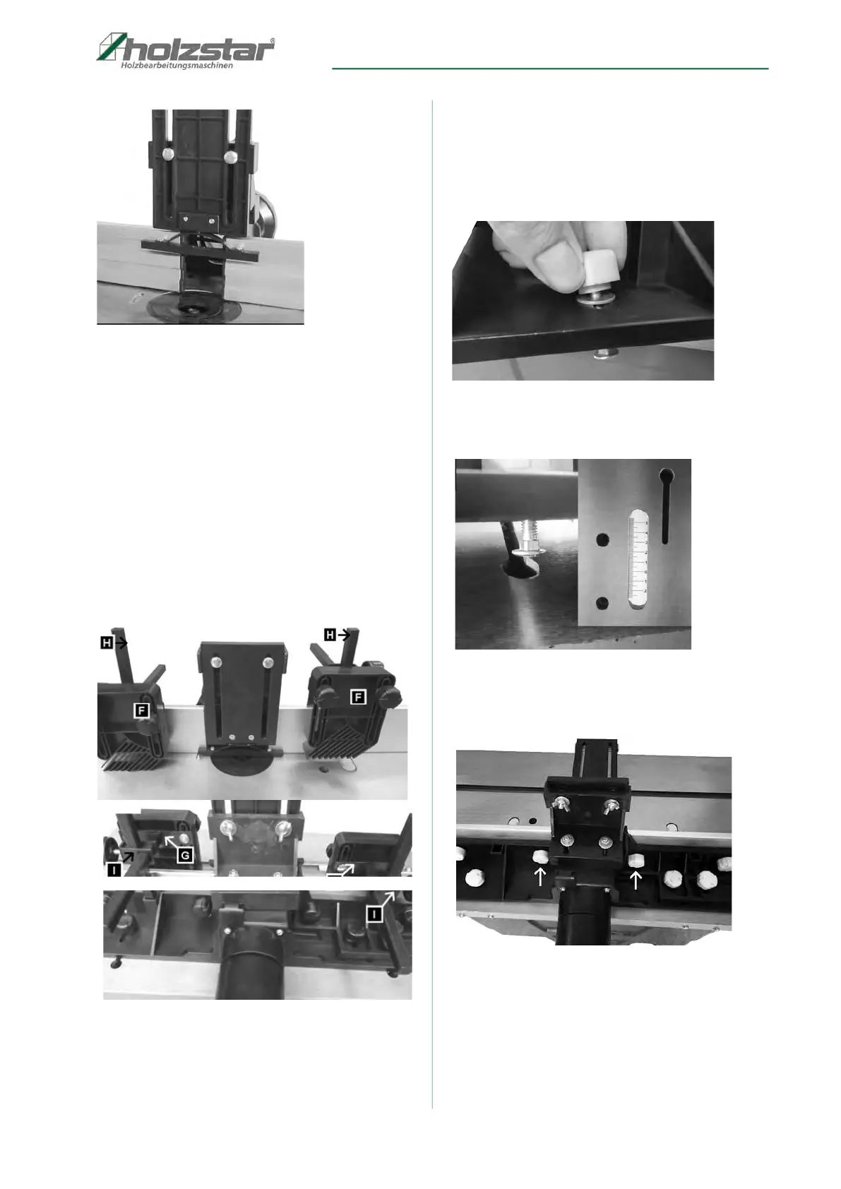
7.4 Installing the pressure device
Insert the two square bolts (item H, Fig. 7) into the
square tubes provided and secure using the two
hexagon socket screws.
Secure the two clamps (item I, Fig. 7) on the square bolts
(item H, Fig. 7) using two plastic screws. Then push the
two support plates (item G, Fig. 7) through the openings
in the clamps (item I, Fig. 7). Finally, screw the hold-
down clamps (item F, Fig. 7) to the support plates (item
G, Fig. 7) using 4 carriage bolts, 4 washers and 4 plastic
nuts.
Fig. 7: Installing the pressure device
7.5 Fitting the spindle fence to the
working table
Step 1: Fit the 2 screws with plastic heads together with
the washers into the grooves on the spindle
fence (Fig. 8).
Fig. 8: Installing the spindle fence
Step 2: Guide the heads on the plastic screws through
the openings on the table grooves (Fig. 9).
Fig. 9: Installing the spindle fence
Step 3: Adjust the router fence to the desired position
and tighten the plastic head nuts (Fig. 10).
Fig. 10: Installing the spindle fence