Stack’d Series HOMEGRID Technical
Page 8 Chapter3: How to use Monitoring Software EMS Tools
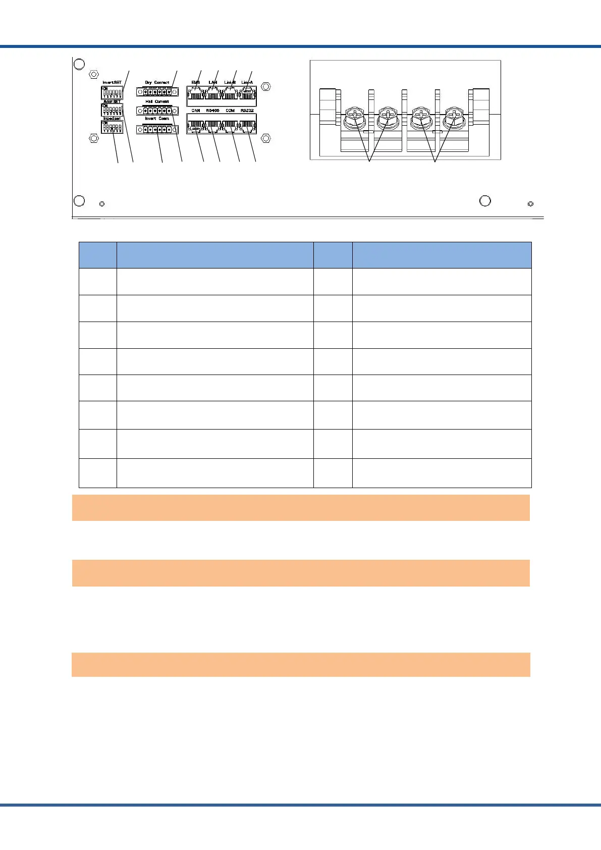
Figure2.4.3Interface definition of Controller module
No. Instructions No. Instructions
1 Inverter protocol dialing switch 9 Parallel communication port B
2 Imped. SET (Reserved) 10 Parallel communication port A
3 Address Dial Switch 11 Inverter CAN communication port
4 Dry Contact (Reserved) 12 Inverter RS485communication port
5 Inverter CAN/ RS485communication port 13 CAN upgrade communication port
6 Hall Current (Reserved) 14 RS232 communication interface
7 Reserved 15 Charge discharge negative electrode
8 Reserved 16 Charge discharge positive electrode
Power switch: turn on/off the input and output of the whole system.
Display screen: the interface can observe the operation status information SOC, SOH,
charging/discharging power, alarm fault indication, charging and discharging status, and system
status of the whole system.
Status code: The code will only be displayed on fault, during if the system is normal the code
will not be shown. The definition of alarm is shown in the table below: