Stack’d Series HOMEGRID Technical
Page 9 Chapter3: How to use Monitoring Software EMS Tools
value
Alarm indication
value
Alarm indication
000 Normal 014 Charging circuit fault
002 Low voltage protection 015 Cell failure
003
Charging over current
protection
016 NTC failure
004
Discharge over current
protection
019
Communication interruption fault of external
equipment
005 Short circuit protection 020
Internal equipment communication interruption
fault
006 Charging high temperature 022 Relay over temperature protection
007 High discharge temperature 023 Copper bus over temperature protection
008 Low charging temperature 025 Lost communication between screen and device
009 Low discharge temperature 051 Total pressure overcharge protection
011 High ambient temperature 052 Total pressure over discharge protection
012
Excessive differential
pressure
053 Low ambient temperature protection
013 Discharge circuit failure 054 MOS over temperature protection
NOTE:
●When the system is charged, the display streamline gathers in the middle, and when it is discharged, the
display streamline disperses to both sides
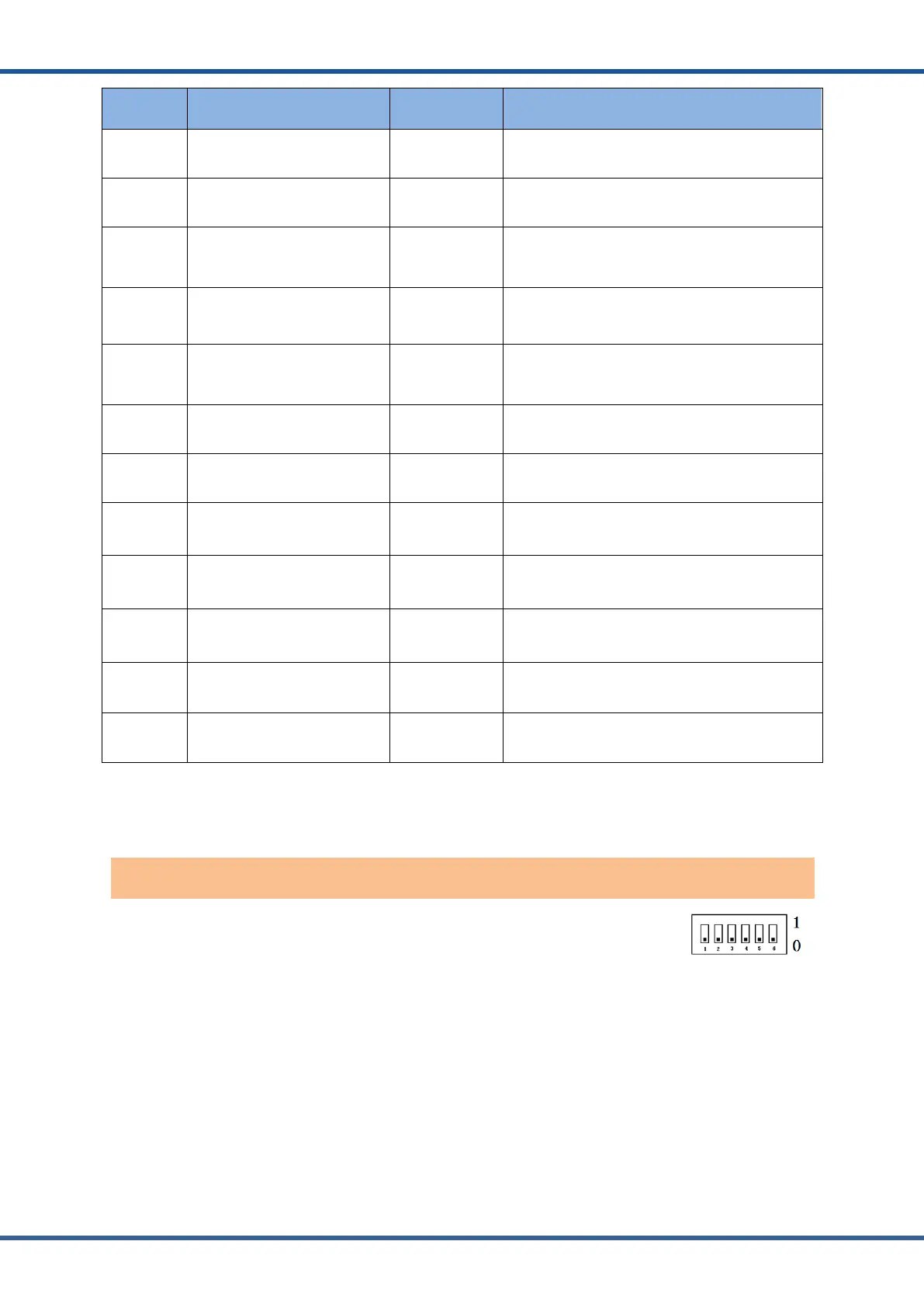
Dial switch: 6-digit dial switch, address "0" and "1", as shown in the figure.
After setting, you need to restart the system and activate it.
When the system groups are in parallel, the communication between two levels is needed. Both
master and slave packets need hardware address configuration, and the hardware address can
be set through the dial switch on the board. The definition of switch is shown in the table below.
Controller address dial switch