Stack’d Series HOMEGRID Technical
Page 10 Chapter3: How to use Monitoring Software EMS Tools
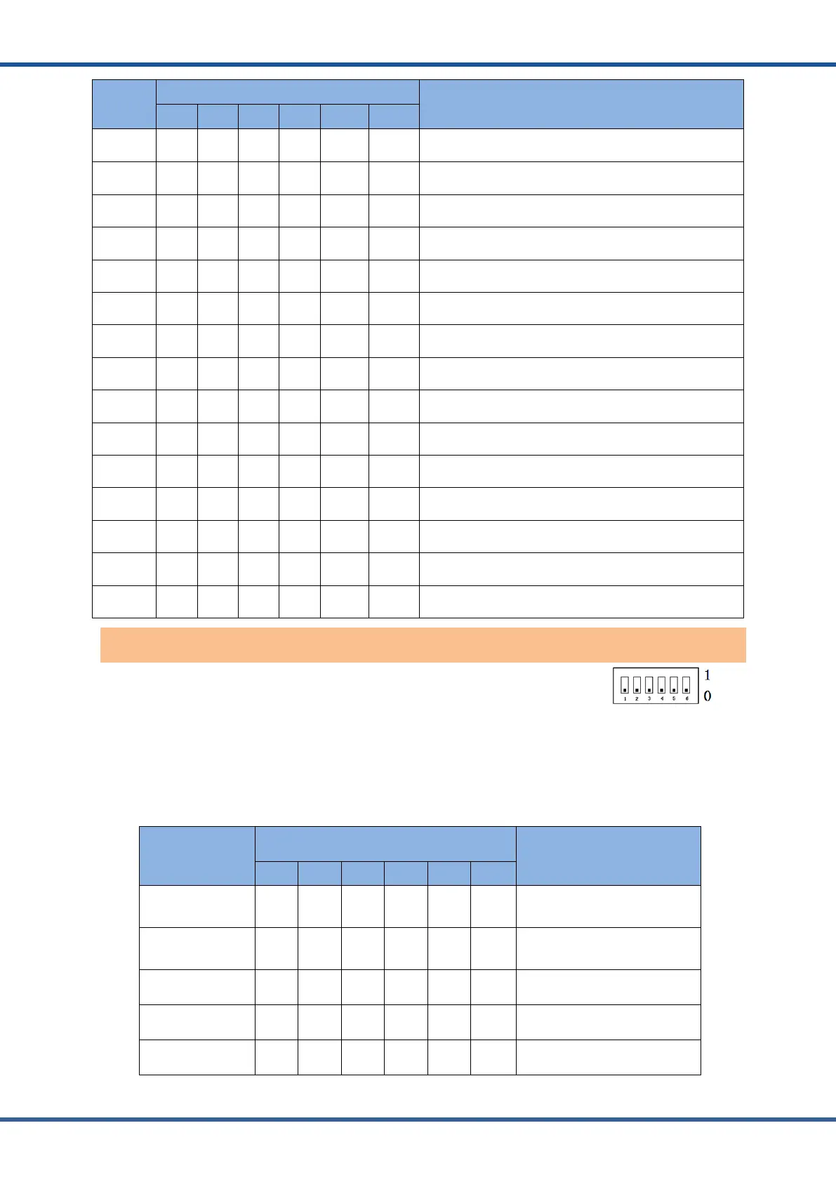
Address
Coding
Dial Code Switch Position
Definition
#1 #2 #3 #4 #5 #6
1 ON OFF OFF OFF NG NG
The host computer can monitor the operation of other
systems by setting the main package
2 OFF ON OFF OFF NG NG Set to Pack2
3 ON ON OFF OFF NG NG Set to Pack3
4 OFF OFF ON OFF NG NG Set to Pack4
5 ON OFF ON OFF NG NG Set to Pack 5
6 OFF ON ON OFF NG NG Set to Pack 6
7 ON ON ON OFF NG NG Set to Pack 7
8 OFF OFF OFF ON NG NG Set to Pack 8
9 ON OFF OFF ON NG NG Set to Pack 9
10 OFF ON OFF ON NG NG Set to Pack10
11 ON ON OFF ON NG NG Set to Pack 11
12 OFF OFF ON ON NG NG Set to Pack 12
13 ON OFF ON ON NG NG Set to Pack13
14 OFF ON ON ON NG NG Set to Pack 14
15 ON ON ON ON NG NG Set to Pack 15
ADD Switch:6 ADD switches,“0”and“1”,refer to picture right.
When the host is connected with the inverter, the host computer needs to
communicate. Hardware address configuration is required on the host, and the hardware
address can be set through the dial switch on the board.
1. Inverter protocol setting function of dial switch 0 ~ 28: The inverter communication
protocol can be changed directly by setting the dial switch, The definitions are shown in the
following table.
Address Coding
Dial Code Switch Position
Definition
#1 #2 #3 #4 #5 #6
0 OFF OFF OFF OFF OFF OFF
Monitoring Software setting
mode
1 ON OFF OFF OFF OFF OFF ZRGP
2 OFF ON OFF OFF OFF OFF Studer_Xtender
3 ON ON OFF OFF OFF OFF Sofar_LV
4 OFF OFF ON OFF OFF OFF Solis_LV
Inverter protocol dialing switch