LIGHTS/METERS/SWITCHES
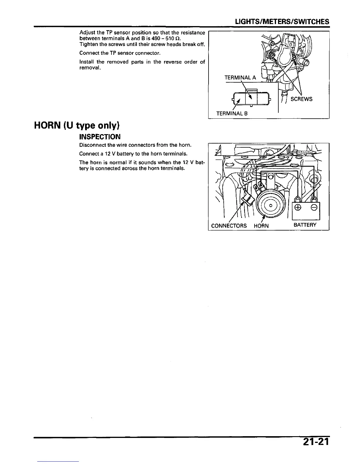
Adjust the TP sensor position so that the resistance
between terminals A and B is 490 - 510 £1
Tighten the screws until their screw heads break off.
Connect the TP sensor connector.
Install the removed parts in the reverse order of
removal.
HORN (U type only)
INSPECTION
Disconnect the wire connectors from the horn.
Connect a 12 V battery to the horn terminals.
The horn is normal if it sounds when the 12 V bat-
tery is connected across the horn terminals.
TERMINAL A
TERMINAL B
SCREWS
e
CONNECTORS HORN
BATTERY
21-21
 Loading...