Accenta/Optima Engineer’s Manual
9
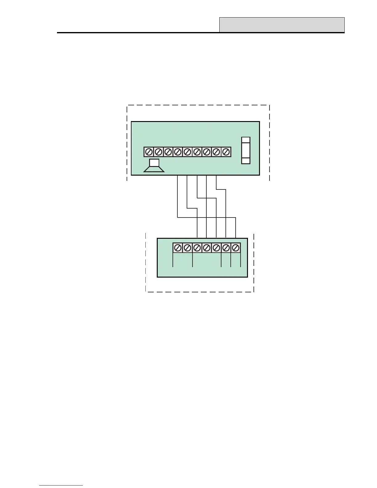
External Siren Output
The external siren is usually installed in a high position from where the siren could be seen and heard.
Terminal TADB are for connection to the external siren. These terminals provide a power/hold-off supply,
sounder trigger and tamper circuit to protect the external siren housing.
Figure 11. External Siren Wiring
The terminals are summarised as follows:
T = Negative (-Ve) tamper return
A = Negative (-Ve) supply (0V)
D = Positive (+Ve) supply (12V)
B = Negative (-Ve) Sounder trigger
Where an external siren without strobe is used, it should be connected to terminals D and B. Terminals T and
A are then used for tamper protection for the housing.
External Siren
-
STROBE
J6
+
TA
SCB
DB
BELL
+
-
SET
1A
BELL/STROBE
F3
Panel
Board
-
STB
+
T
A
D
B
BATTERY
+
-
Board
RTN
HOLD
OFF
TRIG
Siren
Yellow
White
Green
Red
Black
Yellow
White
Green
Red
Black
 Loading...