BACNET® FIXED FUNCTION THERMOSTAT
17 31-00099—01
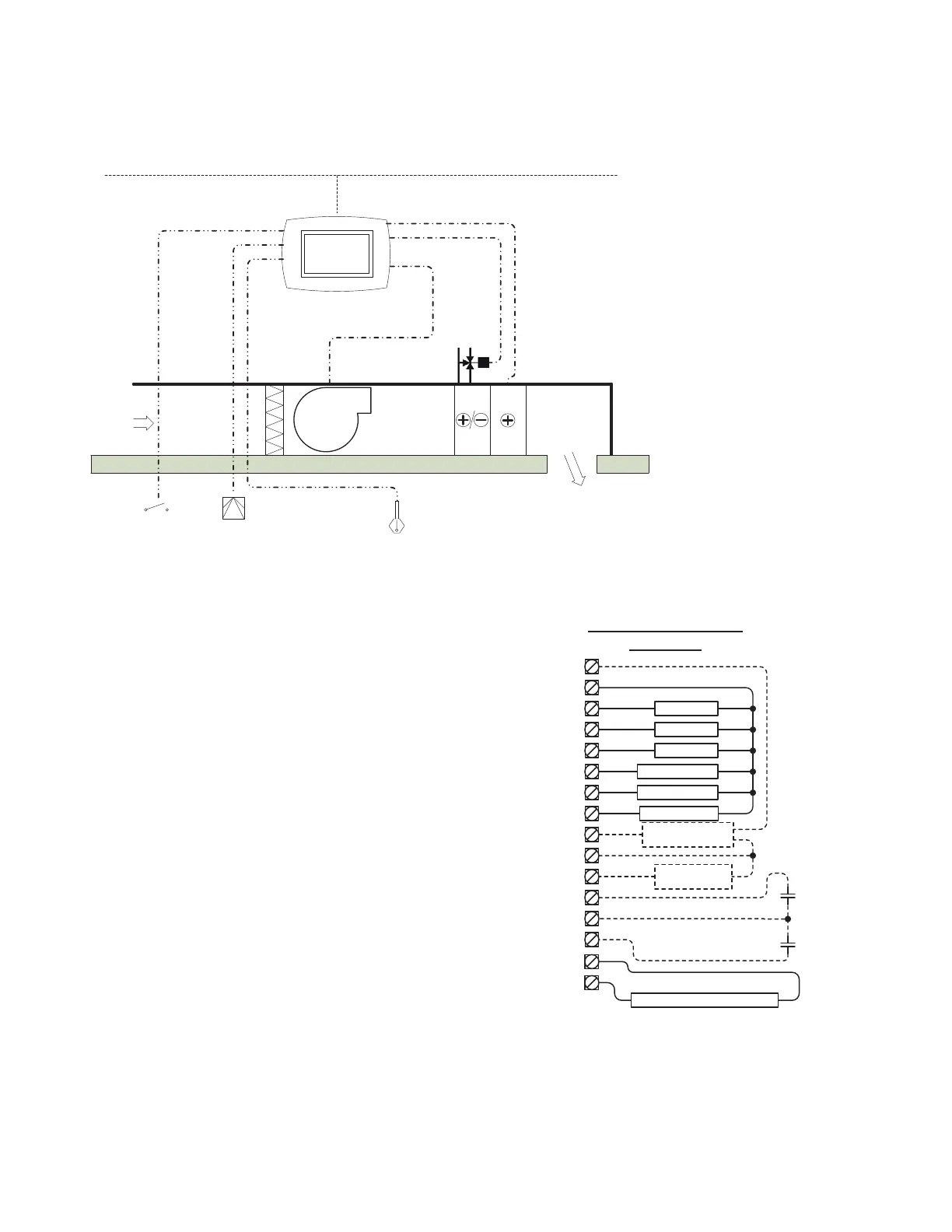
APPLICATION 13 – FAN COIL UNIT – 2 PIPE
Features and Notes
• Three modes of schedule control set by AV-123 –
0 = Single point with offset during occupancy,
1 = Dual setpoint residential – wake, leave, return & sleep,
2 = Dual setpoint with offset occupancy.
• BACnet MS/TP compliant.
• English or metric units.
• Outputs are disabled if BV-2 is off.
• Disable operator access via the display to the schedule
by setting BV-102 to off.
• Onboard schedule can be enabled or disabled (BV-40).
• Cooling or heating is disabled if the fan is off.
• Use up and down arrows on the display to force the unit
into occupancy for four hours.
• Setpoint mode emulates residential thermostat operation.
• Fan can be set to run continuously or cycle on and off for
heating or cooling demands while in Occupancy mode
(AV-17).
• Fan speed will ramp between 0-100% depending on
cooling and heating demands
• Electric heater is enabled if the heating demand is > 70%
• Fan speed selected upon the following settings -
Low Speed – at 20% demand (adjustable in AV-46)
Medium Speed – at 40% demand (adjustable in AV-85)
High Speed – at 70% demand (adjustable in AV-89)
Fan speed deadband set at 2%
• Humidity control can be enabled for un-occupancy (BV-53).
• Use a 10K Type II Thermistor sensor for the strap on water
supply temperature.
DOOR SENSOR, LOW/MEDIUM/HIGH SPEED FAN. THREE POINT FLOATING OR ANALOG COOLING OR HEATING AND ELECTRIC HEATER
Inputs
BI-0:: Motion Detector PIR (optional)
BI-1:: Door/Window Sensor (optional)
AI-2:: Supply Water Temperature
Sensor
Outputs
BO-0:: Fan Low Speed
BO-1:: Fan Medium Speed
BO-2:: Fan High Speed
BO-3:: Cooling or Heating Valve Open
BO-4:: Cooling or Heating Valve Close
BO-5:: Auxiliary Heating
AO-0::
Analog Modulating Cooling or
Heating Valve 0-10V or 4-20mA
AO-1:: Fan Speed Control (optional)
4-20mA VFD
Note: Any I/O listed as “optional” will
require a BV to be set. Refer to the
sequence of operations outlined in
the BACnet FF Thermostat System
Engineering Guide, 31-00098.
MS/TP Network
Digital
Digital
C
M
Digital
3 Point Floating or Analog
Electric
Heater
Digital
Motion Detector PIR
(optional)
Door/Window Sensor
(optional)
Strap on Supply Water
Temperature Sensor
Fan F 1 SS
Fan F 2 SS
Fan F 3 SS
C/H Vlv Op
C/H Vlv Cl
Clg/Htg Vlv
Controller Terminations
2PFC AP 13
GND
5
BO 0
BO 1
BO 2
BO 3
BO 4
BO 5
AO 1
G1
G2
G3
Y1
Y2
EC
0-10Vdc
Com
14
AO 0
C
RC24VAC
1
24V
Com
BI/AI 1
COM
COM
BI/AI 0
EC/VC
VC
FAN VFD
4-20ma
4-20ma
Com
PIR
Motion
Sensor
Aux Htg Stg
W1
Strap on C /O Temp Sensor
Required to monitor water temp in supply pipe
BI/AI 2
Door/Window
Switch
 Loading...