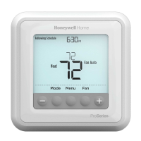
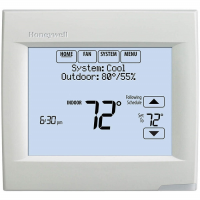
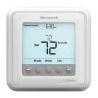
BACNET® FIXED FUNCTION THERMOSTAT
23 31-00099—01
FIELD SERVICE MODE SETTINGS
Items listed below are in order of display via the "Field Service Mode" on the BACnet FF Screen.
Service
Code
Object
Instance
Default
Value
Range Purpose/Function Applications
parameter
applies to.
UC AV-95 85 45.0 to 99.0 Unnoccupied Cooling Setpoint All
UH AV-96 55 45.0 to 84.5 Unnoccupied Heating Setpoint All
CO AV-93 2 0.0 to 20.0 Cooling Offset All
HO AV-94 1 0.0 to 20.0 Heating Offset All
CS AV-99 Calculated From AV-90 Occupied Cooling Setpoint All
HS AV-100 Calculated From AV-90 Occupied Heating Setpoint All
AL AV-97 4 0 to 9.5 Override Limit (hours) All
HI AV-91 78 0.0 to 127.0 Setpoint High Limit All
LO AV-92 62 0.0 to 89.5 Setpoint Low Limit All
SP AV-90 70 Restricted to range set by
AV-92 & AV-91.
Occupant Selected Space Temperature Setpoint. All
AP AV-49 Set this to select the required Application Application Selection range 0 to 18 All
OE BV-2 Off Set to On after completing all
other settings.
Enable Outputs All
HC BV-21 Off On = Heating. Off = Cooling. Reversing Valve Action Heating-Cooling. 0-3, 10
FC AV-17 1 1 = Fan runs continuous,
2 = Fan Cycles with Heating,
3 = Fan Cycles with Cooling.
All
CC AV-26 12 1 to 1440 AC-HP Compressor Cycle Time (mins) 0-3,10
C0 AV-27 3 AC-HP Compressor Minimum On Runtime (mins) 0-3,10
CF AV-18 3 AC-HP Compressor Minimum Off Runtime (mins) 0-3,10
Hc AV-28 3 1 to 1440 Heating Stages Cycle Time (mins)
(if set to 0 or less this will disable heating)
0-5,9,10,13,16,18
h0 AV-29 1 Heating Stages Minimum runtime (mins) 0-5,9,10,13,16,18
hF AV-80 60 Heating Stages Minimum Off runtime (seconds) 0-5,9,10,13,16,18
2C AV-37 3 1 to 1440 2 Position Valve Cycle Times (mins) 8,9,14-16,18
2c AV-38 1 2 Position Valves Minimum runtime (mins) 8,9,14-16,18
c5 AV-64 0 0 to 180 Cooling Valve Stroke Time. (seconds) 6-9,11-18
h5 AV-65 0 0 to 180 Heating Valve Stroke Time. (seconds) 6-9,11-18
2P AV-34 1 1=On/Off. 2=Analog to Binary 2 Position Valve Mode 8,9,14-16,18
FA BV-55 Off On/Off Enable Fan Control display All
cL AV-70 55 Cooling Lockout Temp All
hL AV-72 62 Heating Lockout Temp All
P5 BV-47 Off On/Off Off = Enable AI-0 input as a Space Temperature Sensor,
On = use the internal BACnet FF sensor (AV-104).
0-6,10,17
Sr BV-32 Off On/Off On = Enable AI-0 input as Space Temperature,
Off = OAT
0-6,11,17
F1 AV-46 20 Set by DDC AV-80 minus 2% Auto Fan Start Demand % All
F5 AV-5 0 Fan stop delay (seconds) All
F2 AV-85 0 Medium Speed Fan Setpoint All
F3 AV-89 0 High Speed Fan Setpoint All
uL BV-3 Off On/Off Reverse Standby Logic. All
50 AV-19 4 0 to 12 Standby Heating SetPoint All
 Loading...


