BACNET® FIXED FUNCTION THERMOSTAT
31-00099—01 22
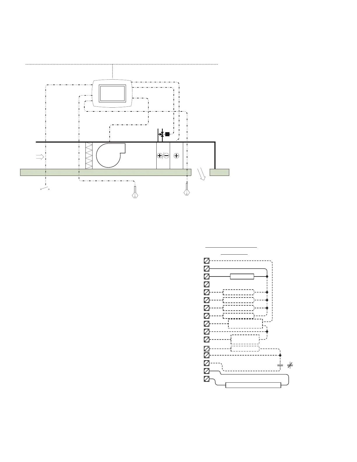
APPLICATION 18 – FAN COIL UNIT – 2 PIPE
Features and Notes
• BACnet MS/TP compliant.
• English or metric units.
• Outputs are disabled if BV-2 is off.
• Disable operator access via the display to the schedule
by setting BV-102 to off.
• Onboard Schedule can be enabled or disabled (BV-40).
• Heating and cooling are disabled if the fan is off.
• Use up and down arrows on the display to force the unit
into occupancy for four hours.
• Setpoint mode emulates residential thermostat
operation.
• Fan can be set to run continuously or cycle on and off for
heating or cooling demands while in occupancy mode
(AV-17).
• Fan control is either start/stop or variable speed control.
• The cooling or heating valve can be controlled by either a
cooling or heating signal or via the supply air
temperature (BV-15).
• Humidity control can be enabled for un-occupancy
(BV-53).
• If door or window contacts are open longer than the
delay time (AV-20) the unit goes into standby mode.
• Humidity control can be enabled for un-occupancy
(BV-12 & BV-53).
• Use 10K Type II Thermistor sensors for the water and
supply air temperature sensors.
TWO POSITION, THREE POINT FLOATING, OR ANALOG COOLING OR HEATING VALVE, ELECTRIC HEATER, ON/OFF OR VFD FAN
Inputs
BI-1::
PIR/Door/Window Sensor
(optional)
AI-0:: Supply Air Temperature
AI-2:: Supply Water Temperature
Sensor
Outputs
BO-0:: Fan On/Off
BO-1:: Not Used
BO-2:: Cooling/Heating Valve
2 Position Open/Close
BO-3:: Cooling/Heating Valve Open
3 Point Floating
BO-4:: Cooling/Heating Valve Close
3 Point Floating
BO-5:: Auxiliary Electric Heating Coil
AO-0:: Analog Modulating Cooling or
Heating Valve 0-10V or
4-20mA (optional)
AO-1:: Fan Speed Control (optional)
4-20mA
Note: Any I/O listed as “optional” will
require a BV to be set. Refer to the
sequence of operations outlined in
the BACnet FF Thermostat System
Engineering Guide, 31-00098.
MS/TP Network
Digital
2 Position Open/Close, 3 Point Floating or Analog
Digital or VSD
Electric
Heater
Digital
Supply Air
Temperature Sensor
(optional)
Standby Detection
(optional)
Strap on Supply Water
Temperature Sensor (optional)
Fan
Clg/Htg Vlv
Clg/Htg V Op
ELEC COIL
Clg/HTG Vlv
Controller Terminations
2PFC AP 18
GND
5
BO 0
BO 1
BO 2
BO 3
BO 4
BO 5
AO 1
G1
Y1
Y2
Y3
W1
EC
0-10Vdc
Com
14
AO 0
C
RC24VAC
1
24V
Com
BI/AI 1
COM
BI/AI 2
COM
BI/AI 0
EC/VC
VC
FAN VFD
4-20ma
4-20ma
Com
Y4
W1
Clg/Htg V Cl
Strap on C /O Temp Sensor
Required to monitor water temp in supply pipe
SA Sensor
Optional
Standby
N.C. or N.O.
 Loading...