BACNET® FIXED FUNCTION THERMOSTAT
31-00099—01 24
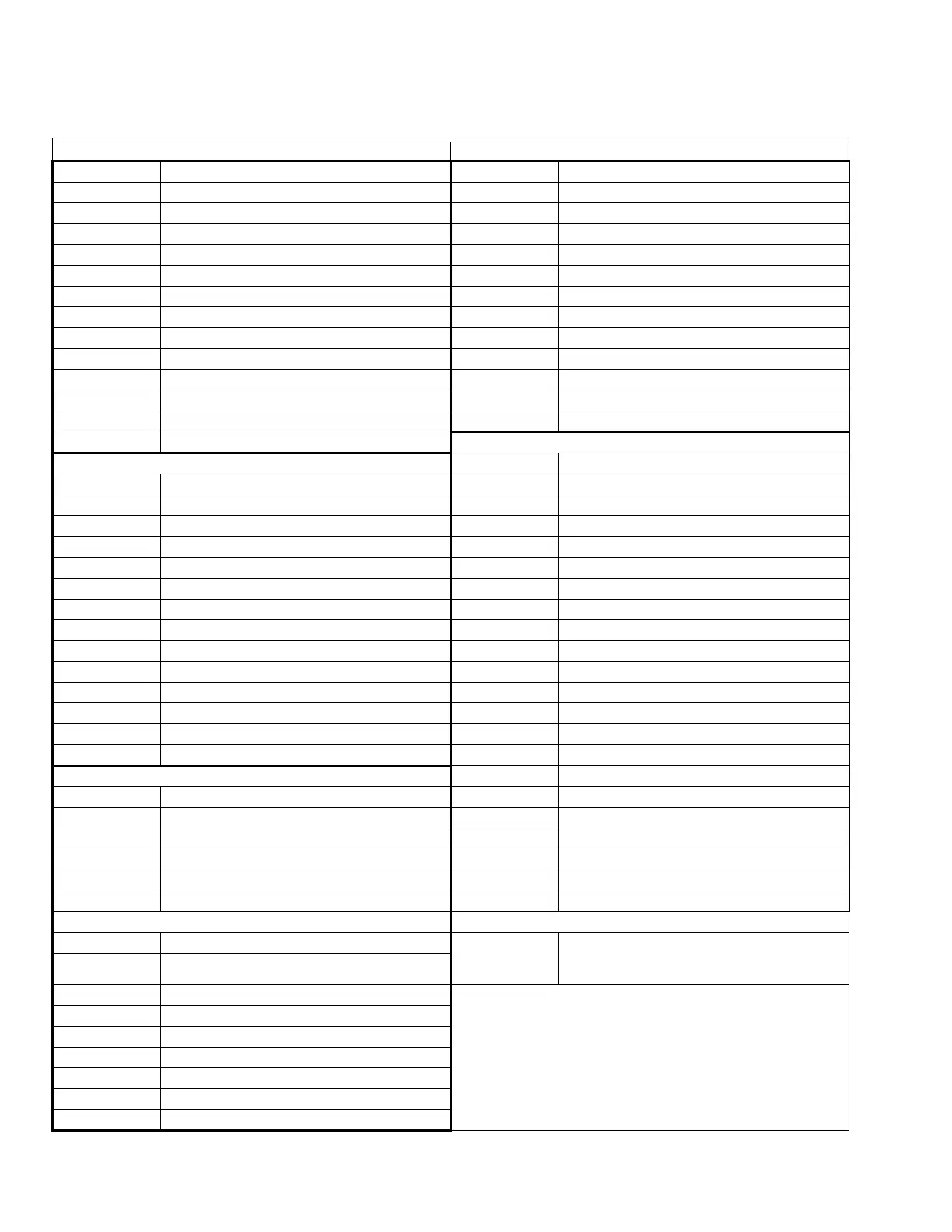
LIST OF MAIN DEVICE OBJECTS
Not accessed via the touchscreen. These are set up with default values.
Fan Control Zone Control
Device Object Label Device Object Label
AV-39 Fan Speed Demand (Analog) % AV-103 Outside Air Temp
AV-5 Fan Stop Delay (Sec) AV-104 Space Temp from (BMS)
AV-82 Fan Runtime AV-12 Supply Air Temp
AV-85 Medium Speed Fan Start SP AV-123 Schedule Module
AV-86 Filter Runtime AV-36 Space Temp used for PI Calc
AV-89 High Speed Fan Start SP BV-124 System Auto Selected
BV-16 Filter Alarm BV-133 Enable Internal Schedule
BV-5 Fan Status BV-32 Enable Remote Sensor (AI-2)
BV-59 Fan Auto - On BV-4 In Standby Mode
BV-72 Fan 3 speed - Low BV-40 Occupied Command
BV-73 Fan 3 speed - Medium BV-47 Enable Remote Sensor (AI-0)
BV-74 Fan 3 speed - High BV-56 Enable BMS Scheduling
BV-80 Enable Fan Speed Control Heating and Cooling Signals
Compressor Control AV-0 Heating Signal
AV-21 Compressor 1 Starts AV-1 Cooling Signal
AV-22 Compressor 2 Starts AV-105 Sensed Humidity
AV-40 AC HP Mode Control AV-13 Heating Valve Demand
AV-68 AC HP Compr Start Demand % AV-18 AC-HP Compr. Min Off (mins)
AV-69 AC HP Compr Stop Demand % AV-27 AC-HP Compr. Min On (mins)
AV-81 Runtime HP Comressor (App 10) AV-41 Heat Signal Proportional Gain
AV-87 Runtime Cooling Stage 1 AV-42 Heating Signal Integral Gain
AV-88 Runtime Cooling Stage 2 AV-43 Cool Signal Proportional Gain
BV-21 Reverse Valve Action, 1 = cool AV-44 Cooling Signal Integral Gain
BV-22 1 = Cooling Locked Out AV-57 Calc. Compr. Off time (sec)
BV-27 1 = Heating Locked Out AV-58 Calc. Compr. Cycle time (sec)
BV-6 HP Fun Request AV-59 Calc. Compr. Mins on (sec)
BV-7 Fan Request (AC Cooling) AV-8 Cooling Valve Demand
BV-31 WS HP Water Loop OK AV-83 Runtime Heat Stage 1
Economizer Control AV-84 Runtime Heat Stage 2
AV-10 Economizer Position BV-1 1 = In Heating Mode
AV-63 Econ. Damper Stroke Time BV-12 1 = Dehum Mode is On
AV-60 Supply Air Low temp Limit BV-52 RH Fan Circ Cycle time (mins)
AV-66 Econ. Min. Position BV-27 Heating Lockout
AV-11 Float Point Econ. Position BV-28 Cooling Lockout
BV-20 Supply Air Low Limit Alarm BV-24 Supply Temperature Valid
Occupancy/Standby Residential Mode
BV-4 In Standby Mode AV-129 Sets the number of occupancy periods,
2 = wake and sleep,
4 = wake, leave, return and sleep.
BV-63 Door Open
BV-62 No Motion Since Door Closed
NOTE: This is a selection of some of the device objects.
For the full list refer to the BACnet FF Thermostat
System Engineering Guide, 31-00098.
BV-149 Wireless Installed
BV-67 Occupied
BV-60 Window/Door Open (Wireless)
BV-61 No Motion Since Dr Clsd (Wireless)
AV-20 Standby Delay (Sec)
BV-81 Hotel Mode
 Loading...