บริษัท เอดีดี เฟอร์เนส จํากัด
ADD FURNACE CO.,LTD.
44 ซอยบรมราชชนนี 70 ถนนบรมราชชนนี แขวงศาลาธรรมสพน์ เขตทวีวัฒนา กรุงเทพฯ 10170
โทร: 02-888-3472 โทร: ออกแบบ:08-08-170-170 แฟกซ์: 02-888-3258
https://www.add-furnace.com E-mail: sales@add-furnace.com
ADJUSTMENTS AND CHECKOUT
Adjust Detector Sighting
With the flame detector installed and the burner running,
adjust the sighting position of the detector for optimum flame
signal. It is suggested that a volt-Ohm meter with a minimum
sensitivity of one megohm/volt and a zero to fi e or ten Vdc
scale be used for R7861 amplifier flame signal
measurements.
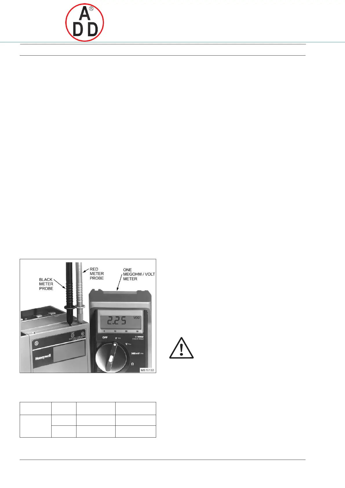
Measure the flame signal as illustrated in Fig. 11. Be careful
to make the proper connections of positive (red) meter lead
to positive (+) control jack and negative (black) meter lead
to negative (-) or (-Com) jack with 7800 SERIES controls.
When the 7800 SERIES control has the keyboard display
module, a zero to five Vdc voltage is displayed on the
module. On SLATE devices expect zero to 8 Vdc.
NOTE: The flame Signal must be stable.
Use a multimeter when measuring the flame
signal or read the display.
Move the detector and sight pipe around to sight the flame
from various positions and angles. Try to get a maximum
steady (or stable) reading on the meter. The signal must be
above the minimum acceptable voltage listed in Table 1.
Measure the flame signal for the pilot alone, the main burner
flame alone, and both together (unless monitoring only the
pilot flame when using an intermittent pilot, or only the main
burner flame when using direct spark ignition). Also
measure the flame signal at low and high firing rates and
while modulating in between (as applicable). With the
detector in its final position, all required flame signals
must be steady (or stable) and as specified in Table 1. If
you cannot obtain the proper signal, refer to the
Fig. 11. Measuring voltage flame Signal with 7800 SERIES
controls
Table 1. Flame signal
Pilot Turndown Test
If the detector is used to prove a pilot flame before the main
fuel valve(s) can be opened, perform a pilot turndown test
before welding the sight pipe into position. Follow the
procedures in the flame safeguard control instructions and
in the burner manufacturer instructions.
Ignition Spark Response Test
Test to make certain that ignition spark is not actuating the
flame relay in the flame safeguard control.
A Close the pilot and main burner manual shutoff valves.
B Start the burner and run through the ignition period.
Ignition spark should occur, but the flame LED must not
light. The flame signal should not be greater than 0.25
Vdc.
C If the flame relay does pull in, reposition the detector
farther from the spark, or relocate/resight the detector
to eliminate/reduce the detector response to reflected
UV radiation. It may be necessary to construct a barrier
to block the ignition spark from the detector view.
Continue adjustments until the flame signal due to
ignition spark is less than the flame signal values
Response to other Ultraviolet Radiation Sources
Some sources of artificial light produce small amounts of
ultraviolet radiation. Under certain conditions, an ultraviolet
detector responds to them as if it is sensing a flame. Do
not use an artificial light source to check the response of an
ultraviolet flame detector. To check for proper detector
operation, conduct flame failure response tests under all
operating conditions.
Weld the Sight Pipe
When the flame signal is acceptable after all adjustments
are made, remove the detector, and weld the sight pipe in its
final position (if you are using a swivel mount the pipe may
already be welded). Then reinstall the detector.
Final Checkout
Before putting the burner into service, check out the
installation using the checkout procedures in the
instructions for the appropriate flame safeguard control.
After completing the checkout, run the burner through at
least one complete cycle to verify correct operation.
CAUTION
Do not put the system into operation until all
checkout tests in the instructions for the
appropriate flame safeguard control and any
others specified in the burner installation
instructions are satisfactorily completed.
min. acceptable
steady signal
max. acceptable
steady signal
 Loading...